Controlled Switching — Buyer´s Guide
D-1
Edition 2, 2006-09
Capacitor Banks and Harmonic Filters Application
Switching of Capacitor Banks and Harmonic Filters
Control of Closing Operations
Switchsync
TM
circuit breaker controllers for
shunt capacitor banks and harmonic filters
are normally used for control of closing op-
erations.
When a capacitor bank or harmonic filter
bank is de-energized, it takes a certain time
for residual charge to disappear. In order to
avoid energizing a capacitor bank while still
charged, a time relay is normally applied for
blocking of the circuit-breaker mechanism.
Build-in discharge resistors will make sure
that the bank is discharged when the inter-
locking has expired.
A typical relay setting is 10 minutes from
opening of the circuit-breaker to the earliest
possible subsequent closing operation.
A discharged capacitor is similar to a mo-
mentary short-circuit when connected to a
power source. If energized when the source
voltage is high, the connection results in volt-
age and current transients that may cause
serious problems. Depending on the network
configuration, the voltage surge may cause
dielectric breakdown somewhere in the high
voltage network, and low voltage equipment
may suffer insulation damage or malfunc-
tion. With back-to-back capacitor banks,
the inrush current may have high frequency
and high amplitude. In extreme cases, it may
threaten the mechanical integrity of both the
capacitor bank and circuit breaker. Control-
ling the circuit breaker to energize a capaci-
tive load at zero voltage across the contacts
will eliminate harmful transients.
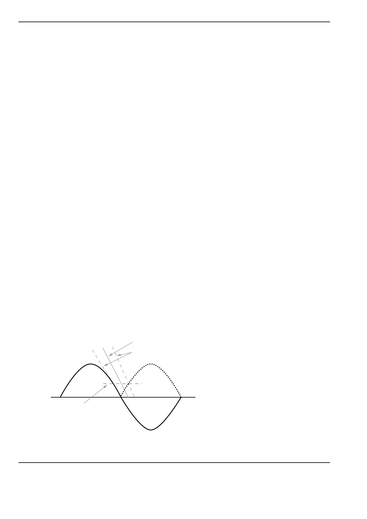
Figure 1. Energizing at voltage zero. The nominal making target
is set slightly after voltage zero in order to minimize influence of
statistical variations.
Upon a closing operation, the contacts in a
circuit breaker pole will have a dielectric with-
stand capability that rapidly decreases from
a high starting value towards zero, when
the contacts touch. This property is often
referred to as RDDS, Rate of Decrease of
Dielectric Strength, of the circuit breaker.
In an ideal case, the circuit breaker con-
tacts should touch exactly when the voltage
across the contacts is zero. For this to be
possible, the RDDS of the circuit breaker
needs to be higher than the rate-of-fall of the
applied voltage close to zero. In reality there
will always be a certain scatter in closing
speed and dielectric withstand characteris-
tics of the contacts. In order to minimize the
adverse effect of such statistical variations
and due to the limited speed, the nominal
making target is therefore set slightly after
voltage zero, as illustrated in Figure 1.
Figure 2 shows by means of an example how
efficiently controlled switching eliminates the
harmful switching transients related to ener-
gizing of a capacitor bank.
Even in a very unlikely case with the most
unfavorable statistical scatter of closing time
and dielectric withstand characteristics; the
switching transient would be decreased to
less than 30 % of what may occur in an un-
controlled situation.
Nominal RDDS characteristics of the circuit breaker
Statistical scatter
Absolute value of
applied voltage
Max pre-striking voltage
 Loading...