Controlled Switching — Buyer´s Guide
E-1
Edition 2, 2006-09
Shunt Reactors Application
Shunt Reactor Design and
Operation
Shunt reactors are mainly used in transmis-
sion networks. Their function is to consume
the excess reactive power generated by
overhead lines under low-load conditions,
and thereby stabilize the system voltage.
They are quite often switched in and out on
a daily basis, following the load situation in
the system. Shunt reactors are normally con-
nected to substation busbars, but also quite
often directly to overhead lines. Alternatively,
they may also be connected to tertiary wind-
ings of power transformers. The reactors
may have grounded, ungrounded, or reactor
grounded neutral.
Shunt reactors normally have iron cores with
integrated air gaps. Due to the air gaps, the
iron cores cannot be significantly saturated,
and the reactors therefore will have a reason-
ably linear behavior during energizing events,
for example.
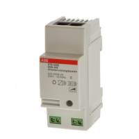
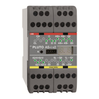
Three-phase shunt reactors may consist of
three separate single-phase units, or be com-
plete three-phase units with common core
and tank. Common, three-phase cores may
be of either five-leg (alternatively shell type) or
three-leg design, see Figures 1a and 1b. Five-
leg cores and shell type cores are mainly used
for transmission voltages. They make the
three phases magnetically independent, while
three-leg cores lead to magnetic coupling be-
tween the phases. The type of core - together
with the winding arrangement (Y- or D-con-
nection) and grounding conditions - therefore
influences the switching sequences utilized for
controlled switching.
Switching of Shunt Reactors
Medium voltage reactors, connected to ter-
tiary windings of transformers, in most cases
have air-insulated windings without iron
cores.
Use of Neutral Reactors
For line connected shunt reactors, an ad-
ditional single-phase reactor (neutral reactor)
is sometimes connected between neutral
and ground. The purpose of this reactor is to
increase the overall zero sequence reactance
of the overhead line. In this way, the fault cur-
rent is kept small in the event of single-phase
line faults cleared by single-pole opening of
the line breakers. As a result, there will be a
high probability that the arc at the fault loca-
tion is extinguished and that the reclosing
operation is successful.
Opening Operations: Chopping
Overvoltages and Reignitions
In addition to the inductance of the winding,
a shunt reactor always has some stray ca-
pacitance, in the windings, the bushings, and
in the connecting leads. When a reactor is
de-energized, the voltage across it will oscil-
late with the natural frequency determined by
the inductance and stray capacitance. The
oscillation frequency is typically a few kHz.
Due to chopping (premature interruption) of
the current slightly before the natural current
zero, the oscillating reactor voltage will have
higher amplitude than the supply voltage.
For modern SF
6
circuit breakers, typical
Figure 1a.
Three-leg (limbed) shunt reactor core
Figure 1b.
Five-leg (limbed) shunt reactor core with three
wound limbs
1= Magnetic flux phase R
2= Magnetic flux phase S
3= Magnetic flux phase T
1
2
3
1
2
3