Controlled Switching — Buyer´s Guide
F-2
Edition 2, 2006-09
Application Power Transformers
Switching of No-load Power Transformers
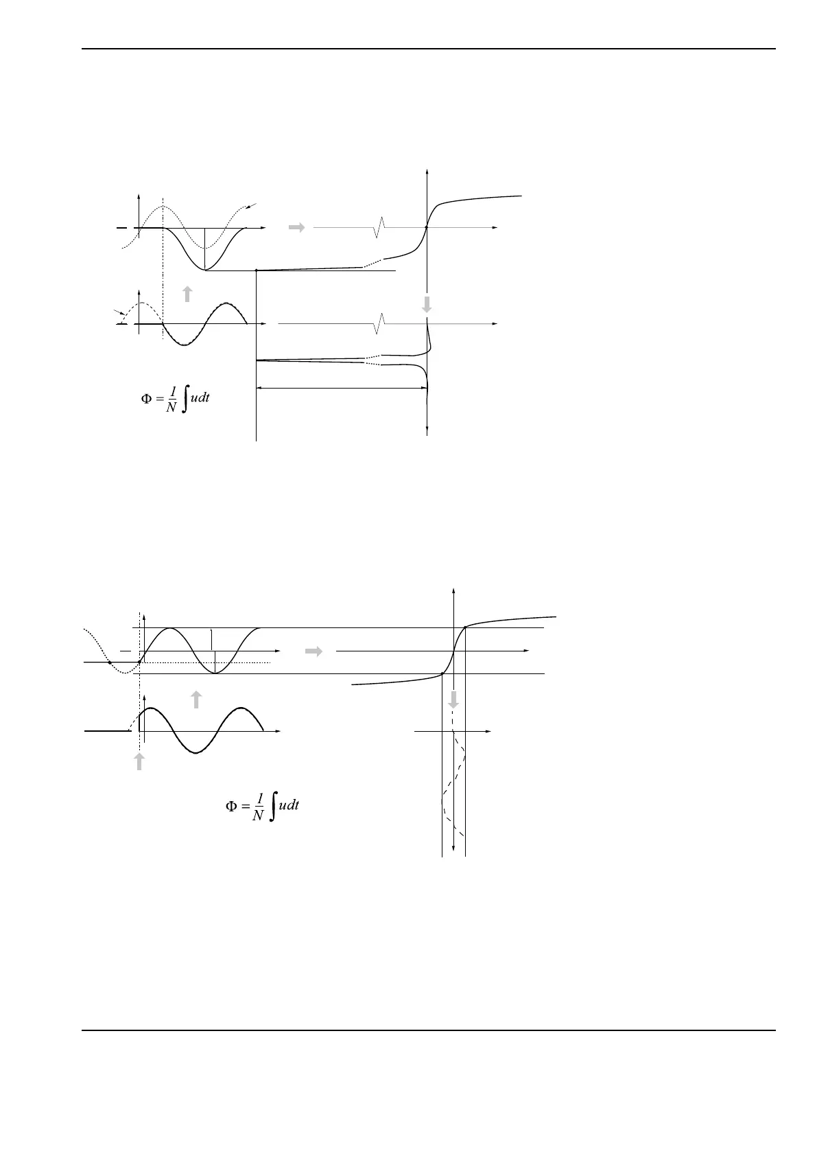
Flux asymmetry may be introduced at energizing by making at unfavorable instants and due to magnetic
inertia as shown in Figure 2.
The solution to create flux symmetry at energizing (to imitate the steady-state condition) is to make at in-
stants where the prospective flux meets the residual flux. An example of an energizing intended to result in
flux symmetry is shown in Figure 3. The transformer is energized at an instant where the prospective flux
equals the residual flux.
The described method requires that the residual flux level is known by measurement (integration of the load
side voltages at interruption) or has been determined by a previously performed controlled interruption.
It is assumed that the residual flux remains unchanged from the de-energizing until the next energizing.
Flux
Flux symmetry
Time
0
Time
0
Flux
Magnetising
current
Current
Time
kA
Voltage
Energizing
instant
Prospective
voltage
Prospective flux
No
residual
flux
High inrush current as a result
of bad selected making instant.
Flux starts off from the residual
flux level and with prospec-
tive wave shape but an offset
is introduced due to magnetic
inertia.
The example shows transformer
having no residual flux.
Flux
Flux symmetry
Time
0
0
Time
Flux
Magnetising current
Current
Time
Voltage
Residual
flux
Minimized inrush current as a
result of selection of optimized
making instant (where residual
flux meets the prospective flux)
Figure 3. Ideal making instant taking into account the residual flux
Figure 2.
High inrush current resulting from bad selected making instant.