Controlled Switching — Buyer´s Guide
F-5
Edition 2, 2006-09
Switching of No-load Power Transformers
Power Transformers Application
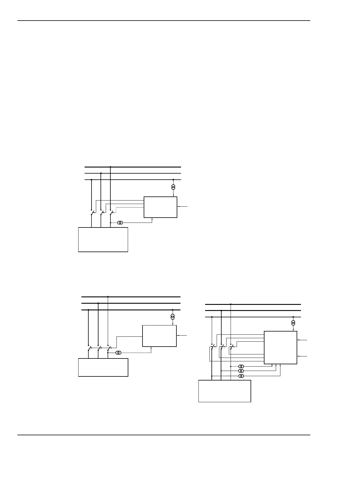
Control of Closing Operations,
Residual Flux Disregarded.
When residual flux may be disregarded, it is
sufficient to control the closing operations
by means of the Switchsync E113 only. This
straight-forward method will limit the high-
est inrush current magnitudes even if there
should be residual flux. For this reason, it
may also be applied in cases with residual
flux - or with unknown residual flux - even
though better results are obtained by use of
the Switchsync F236 or T183, and the asso-
ciated methods with controlled opening and
closing operations or determination of the
residual flux respectively.
Single-pole operated circuit breaker
Three-pole mechanically staggered operated
circuit breaker
Control of Closing Operations, after
Controlled Opening Operations
The opening operations of the breaker are
controlled in order to achieve a defined and
repeatable residual magnetic flux in the trans-
former core. The procedure is normally to
interrupt the no-load current close to a natural
zero passage, which results in minimum flux
in the core. The subsequent closing opera-
tion is then controlled in order to minimize
the inrush current, based on this knowledge.
Sometimes, however, a higher value of re-
sidual flux is chosen, as this will be associ-
ated with lower pre-arcing stress of the circuit
breaker at the subsequent closing operation.
This also improves the precision of the target-
ing process.
The method is suitable for regular planned
switching of transformers under no-load con-
ditions. It is applicable in situations where the
same circuit breaker will always perform the
making and breaking operations. If a trans-
former could be switched by different circuit
breakers from time to time, such as in double
breaker or breaker-and-a-half configurations,
control logic must be applied to ascertain that
the same circuit breaker will also perform the
next energizing operation. A suitable control-
ler type is the Switchsync™ F236.
The circuit breaker should be single-pole
operated. Three-pole operation is unsuitable
since relevant mechanical staggering cannot
be arranged.
Note: In cases when the transformer windings are
inter-coupled, it is sufficient to arrange voltage
measurements for the adaptive function in one
phase only.
Note: Coupled phases lead to simultaneous voltage
start in the three windings. Therefore, only one ad-
aptation signal is needed (can be used).
Note: Voltage signal, from the first energized winding,
is used for the adaptive function of the controller.
For circuit breakers seldom operated, however, com-
pensation may be a better solution than adaptation
control since a substantial change of ambient condi-
tions may appear between two consecutive opera-
tions.
For permissible connections of staggered circuit
breakers, see separate appendix.
R
S
T
Load:
No-load Power Transforme r
with Neglig ible or Unknown
Remanence
Switchsync
E113
C
in
C
out
U
ref
R
S
T
Switchsync
E113
U
ref
C
in
C
out
Load:
No-load Power Transformer
with Inter Coupled Phases
and Negligible or Unknown
Remanence
R
S
T
Switchsync
F236
O
in
C
in
O
out
Load:
No-load Power Transformer
without Inter Coupling
between Windings and
with Substantial Remanence
C
out
U
ref