Controlled Switching — Buyer´s Guide
L-2
Edition 2, 2006-09
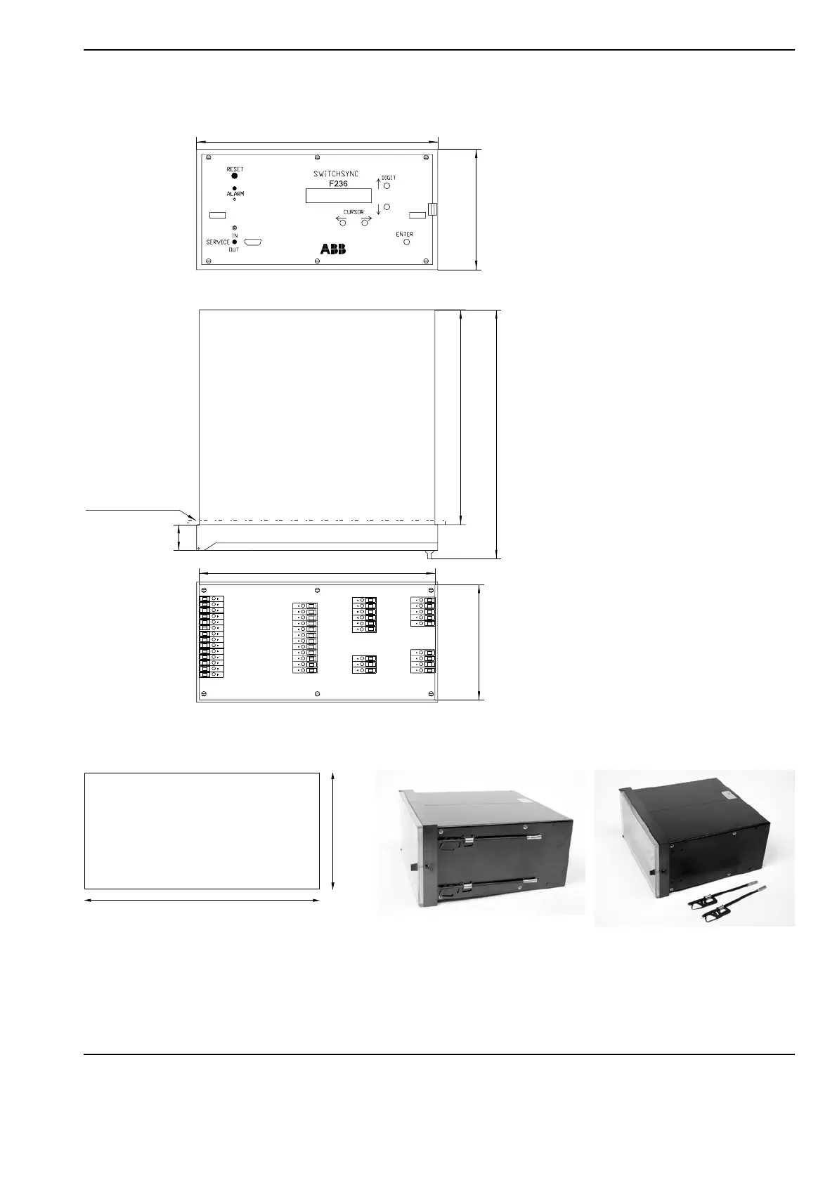
Dimensions for Switchsync
TM
F236, L183 and T183
Technical Information Drawings
Panel thickness 2.5-5 mm
3
1
2
5
7
2
9
8
2
8
2
1
3
8
1
4
4
2
8
8
Mounting Hole Dimensions Mounting
Front view
Top view
Rear view
The side mounted ”snap-on” counter screws shall be removed to allow for the
controller to enter the hole in the panel.
In final position the screws are easily snapped back and tightened.