ABB Transformer Protection Unit 2000R
5-1
Interfacing with Relay
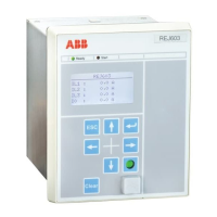
Man-Machine Interface (MMI)
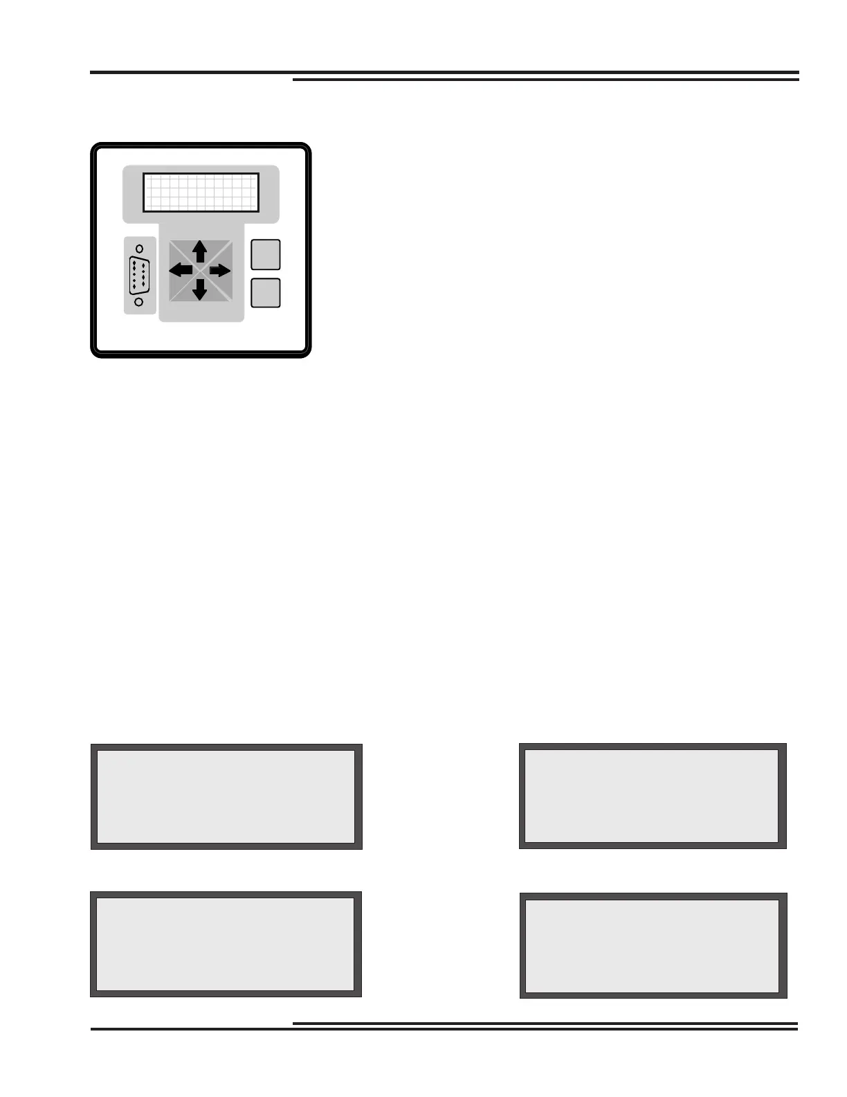
The man-machine interface (MMI) on the front panel consists of a four-line
liquid crystal display (LCD) with twenty characters per line, six push-buttons
(keys) and thirteen LED targets. Press the Enter <E> key to access the
Main Menu. Use the up and down arrow keys to move through the various
menus and to change the character value when you enter the alphanumeric
password. Use the Enter <E> key to select the desired menu or desired
value when you change settings.
Use the left and right arrow keys to decrease and increase, respectively,
setting values or record numbers. You can also use them to move from left
to right within the password string. Hold down or repeatedly press the arrow
keys to change the setting value.
Use the clear <C> key to return to the previous menu. You can also use the <C> key to:
• reset LED targets and the LCD after a fault (push <C> once)
• scroll through all metered values (push <C> twice)
• reset the peak demand values (push <C> three times)
Perform a system reset by simultaneously pressing the <C>, <E> and up arrow keys. This resets the
microprocessor and re-initiates the software program. During a system reset, no stored information or settings are
lost.
The following displays and menus are available through the MMI:
• Continuous Display—the enabled settings table and all currents
• Post-Fault Display—fault currents for last fault until targets are reset
• With optional VT inputs installed, Continuous Display and Post-Fault Display show currents and voltages
MMI Displays
Metering Display (Continuous)
(without optional VT inputs)
Ø
Ia1: 2 Ia2: 2
Ib1: 2 Ib2: 2
Ic1: 2 Ic2: 2
In1: 0 Ig2: 2
Ia2: 500 KVan: 13.00
Ib2: 500 KVbn: 13.00
Ic2: 500 KVcn: 13.00
In2: 0 Prim Set Ø
Metering Display (Continuous)
(with optional VT inputs)
Display After a Fault Interruption
Ø
Diff Fault Rec 1
Fault # 7
Active Set Prim
Date 17 Aug 1995
Main Menu
Ø
MAIN MENU
Meter
Settings
Records
C
E
Figure 5-1. MMI Access Panel
 Loading...