14 VD4X INSTRUCTION MANUAL
—
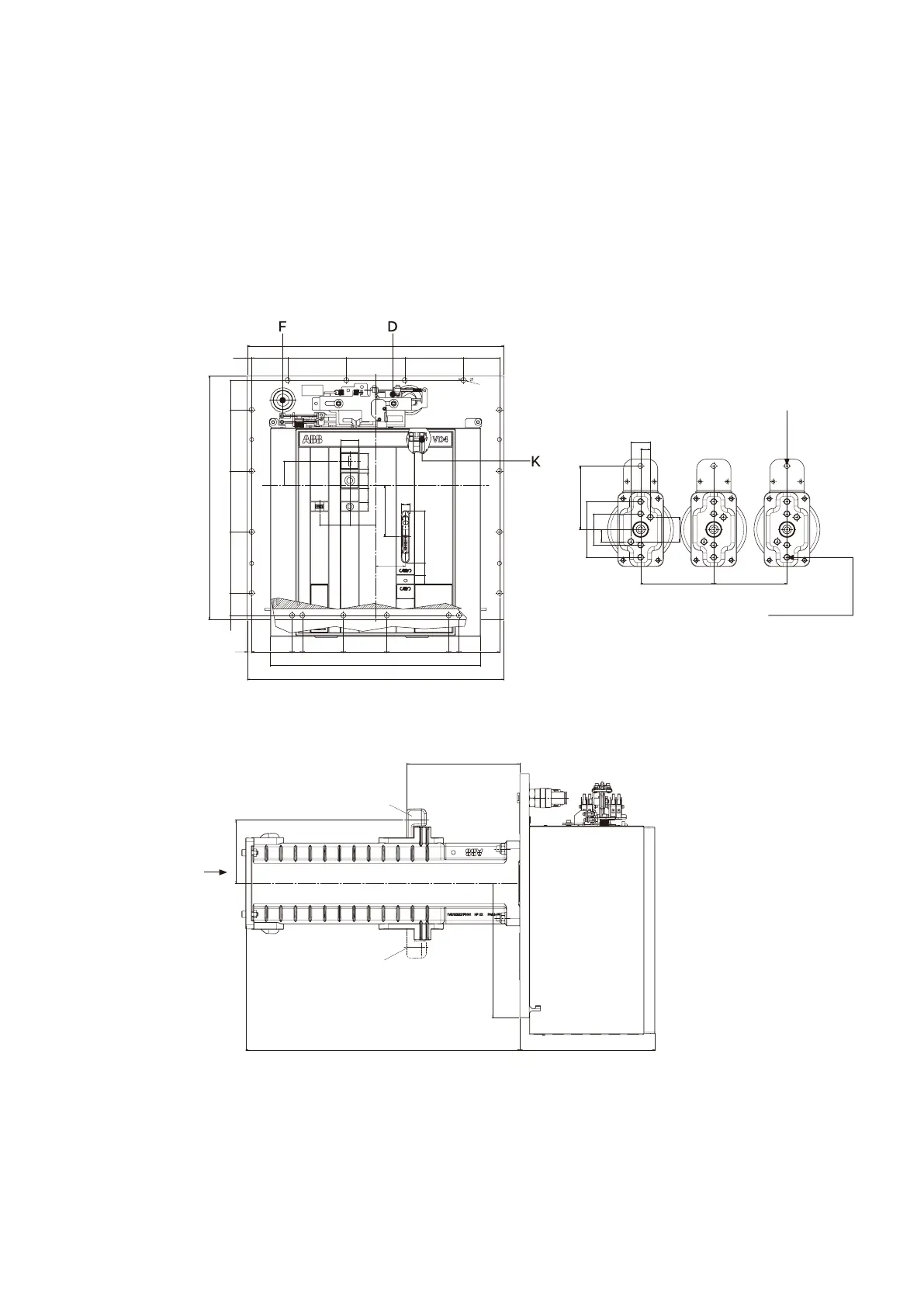
Figure 2/7:
Dimensional drawing
of circuit-breaker,
type VD4X, 3612-31 &
4012-25, p150.
A1
Terminal for
conductor bar
M12
A2
Frontal terminal for
conductor bar
M12 / 30 deep
Terminal for
rated current
• …1250 A
A
9 74
120
120 74
526
61125125125
500
10
526
83 9 21 84 89 127 21 83
46 9
120
62 53
81 82 23 8 23
36
17
107
81 5.52
36
61
431
104.7
50.2
232
276.5
562
±1.5
130
275
1)
1)
130
57
23 23
57
150 150
40
20
25
50
120
120
74
526
10
526
21 84 89 127
21 83
120
62 53
81 82 23
8
23
36
17
107
81 5.52
36
61
431
104.7
232
276.5 562
±1.5
130
275
1)
1)
130
57
23 23
57
150 150
40
20
25
50
61125125125
500
10
526
83 9 21 84 89 127 21 83
46 9
62 53
81 82 23 8 23
36
17
107
81 5.52
36
61
431
104.7
50.2
562
±1.5
130
275
1)
1)
130
57
23 23
57
150 150
20
25
50
A
1) Connection for conductor bar
depends on switchgear and is
positioned above or below the
pole.
A1 = Terminal for conductor bar
A2 = Front terminal for conductor bar
D = Pressure sensor for circuit-breaker compartment
F = Filler connector for circuit-breaker compartment
K = Plug
—
Figure 2/7