Page 17
EXERCISE 21 : SIGNAL REMOVAL - BUS DISABLE OUTPUT
ACTION
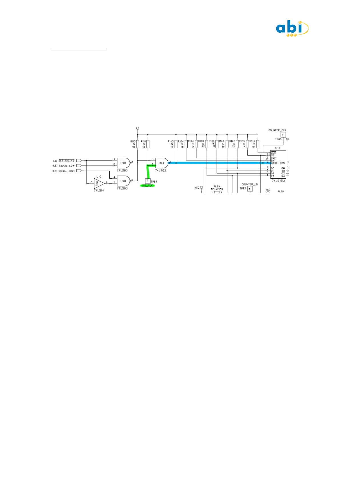
Attach clip to U15 (74LS161).
Identify and attach the Bus Disable Output (BDO) cable as shown in Schematic. (If
Schematics are not available identify the clock signal by using the MIS Oscilloscope). Press
START on the IC tester and observe the SIG Pin 2. Attach a BDO LOW (Green) to TP84 DIS
CLK and observe change to signal.
Note the Truth Table test will fail, as this IC requires a ground clip please go to the next step.
DESCRIPTION
Signals do not always cause device failures, in cases where they causes intermittent bad
comparisons also, it is advised the attempts are made to Stop the signal from affecting the
test. The way of disabling the signal without physically removing the source of the signal
from the board (e.g. a crystal or oscillator). can usually be achieved using the bus disable
output (BDO) cable.
On the training board a clock is generated by a capacitor, a resistor and an inverter which is
then fed through two NAND gates. The clock can be disabled and the output can be made
permanently LOW by using a LOW BDO (green) on the clock buffer IC. By attaching the BDO
Low to TP84 the clock input to the NAND gate is pulled Low so achieving a stable output to
the IC we are testing. This enables the correct logic level to be driven into the IC for the
Truth Table test.
COMMENTS
When using the BDO signals, you must ensure that the point at which you connect the BDO
signal is not directly connected to the IC under test, otherwise the system will be driving itself
and you will get a LOAD indication. Note that the BFL inputs are capable of detecting signals
of up to about 4MHz. Signals above this frequency may not be detected, and you should
always be aware of this if spurious or inconsistent results are obtained. Running tests in loop
mode may show up these undetected signals, especially if the results are inconsistent and
continually changing. INPUT MID LEVELS are also often caused by changing signals above
the detectable frequency.
Either the BDO Low (Green), or BDO High(Red) can be used depending on the circuit
requirements. Alternative means can be used such as a RESET switch or use of BDO on a
CPU RESET pin and device removal.
It is important to remember that the more information you save about a good board the
better the chances of finding the fault when comparing with abad board. In this case you
should save the good device with the SIGNAL present and then in a later step describe how
the SIGNAL should be removed or allow the Truth Table test to Pass. In this way a potential
problem is not removed from the board prior to testing.
 Loading...