Ap863 Users’ Guide Page 15 of 18
1
4
2
6
3
5
8 CONNECTIONS AND EMC PRECAUTIONS
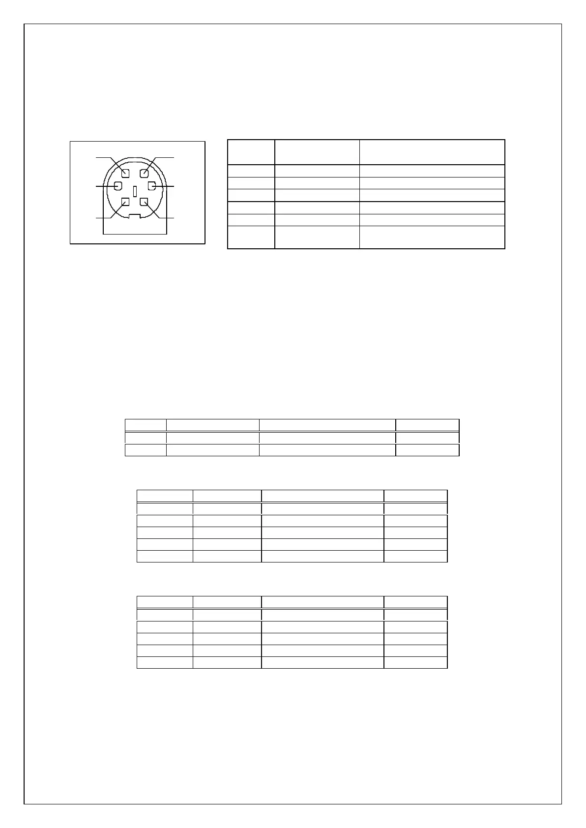
8.1 CONNECTOR DETAILS
A single socket on the rear of the printer combines all data and charger functions.
Printer side: Hosiden TCS7167 6-way Socket (mini-DIN style)
User side: Hosiden TCP7160 6-way Plug & Cable or equivalent
Pin Function AP800-BOC Colour (typical*)
1 TxD Data Output Red
2 BUSY Output White
3 RxD Data Input Black
4 No Connection Yellow
5 Ground ( 0V) Blue
6 Charger (+12V) Green
Screen Frame Ground Screen (separately sheathed,
may be coloured)
Connector viewed from rear of printer. * Cable colours may vary, and the user should verify by measurement.
8.2 COMBINED DATA/CHARGER ADAPTOR CABLES
Various cables with the Hosiden plug pre-fitted at one end are available. The other end of each type
of cable has the following termination:
Ÿ unterminated OEM cable (ASL Product Code AP800-BOC)
Ÿ D-25 data socket and charger jack socket (ASL Product Code AP800-BDC)
Ÿ D-9 data socket and charger jack socket (ASL Product Code AP800-9W-BDC)
The AP800-BDC and AP800-9W-BDC are intended for direct connection to PC COM: ports, and
direct connection with the battery chargers detailed in section ‘8.3 Battery Charger Details‘.
Both the AP800-BDC and AP800-9W-BDC cables feature a co-axial charger socket as follows:
Pin Dimension (mm) Function Ap863 Pin
Inner Inside Ø 2.1 Positive /Charger (+12V ) 6
Outer Outside Ø 5.5 Negative/Common ( 0V ) 5
The AP800-BDC features a D-25 Female socket with the following pinout:
D-25 Pin Name Function (refers to PC) Ap863 Pin
1 FGND Frame Ground Screen
2 TxD Serial Data Output 3
3 RxD Serial Data Input 1
5 & 6 CTS & DSR Busy Input 2
7 SGND Signal Common 0V 5
The AP800-9W-BDC features a D-9 Female socket with the following pinout:
D-9 Pin Name Function (refers to PC) Ap863 Pin
Shell FGND Frame Ground Screen
3 TxD Serial Data Output 3
2 RxD Serial Data Input 1
6 & 8 CTS & DSR Busy Input 2
5 SGND Signal Common 0V 5