Do you have a question about the ABSCO SHEDS 15151SK and is the answer not in the manual?
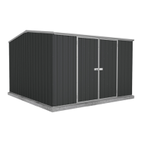
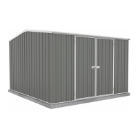
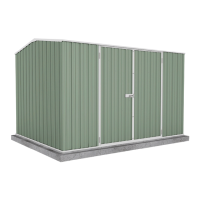
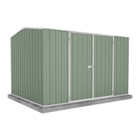
This document describes the N3/C1 Frame Kit for 1.5m wide to 1.5m deep Absco sheds, designed to enhance their wind rating to N3/C1 as per AS4055-2012, making them suitable for specific cyclonic regions. The kit is applicable to shed models 15151GK, 15151SK, and 15141RK.
The N3/C1 Frame Kit provides additional structural bracing and fastening to existing Absco sheds, increasing their resistance to severe storms and cyclonic events. It involves the installation of internal frame sections, additional fasteners, and specific anchoring methods to reinforce the shed's walls, roof, and doors. The kit is intended to be integrated with the original shed structure, and in cases of conflicting information, this document takes precedence over the original non-cyclonic instruction manual.
Absco Sheds come with a Lifetime structural warranty from the date of purchase, covering missing or damaged parts. Warranty registration can be done online or by mail. Claims require proof of purchase. The manufacturer bears the cost of replacing/repairing products and reasonable direct expenses of claiming. For replacements, parts are sent to the nearest reseller within 20 working days. For assessments, an assessor is appointed within 10 working days. The manufacturer bears repair costs. The customer bears assembly costs for replacement products. The warranty does not cover issues arising from improper assembly, storage of corrosive materials, damage from storms/wind/rain/snow/poor foundations, or surface deterioration from unremoved swarf. The product is weatherproof to a certain level, but leaks and condensation can occur. It is intended for garden equipment storage, not articles prone to moisture damage.
| Brand | ABSCO SHEDS |
|---|---|
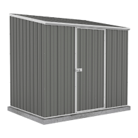
| Model | 15151SK |
| Category | Outdoor Storage |
| Language | English |