The Absima 2.4GHz 2 Channel Radio Control System, model SR2S, is a digital proportional radio control system designed for remote control applications. It utilizes a 2.4GHz frequency band for reliable and interference-resistant operation. This system consists of a transmitter (model FS-T4B) and a receiver (model SR2S).
Function Description:
The Absima SR2S radio control system provides precise and proportional control over remote-controlled models. The transmitter sends control signals to the receiver, which then translates these signals into movements for connected servos and speed controllers. The 2.4GHz digital transmission mode helps prevent external interference, ensuring stable and responsive control. It features a 2-channel transmitter and a 3-channel receiver, allowing for control of steering, speed, and an additional function, typically for battery connection in gas-powered models or other auxiliary functions. The system also incorporates a Failsafe function for enhanced safety.
Important Technical Specifications:
Transmitter (Model FS-T4B):
- Channels: 2
- Frequency Band: 2.4GHz
- Power Resource: 8 x 1.5V "AA" batteries
- Program Type: AFHDS (Automatic Frequency Hopping Digital System)
- Modulation Type: GFSK
- RF Power: <20 dBm
- Static Current: <250mA
- Size: 189mm x 97mm x 218mm
- Weight: 575g
- Color: Black
- Antenna Length: 26mm
Receiver (Model SR2S):
- Channels: 3
- Frequency Band: 2.4GHz
- Program Type: AFHDS
- Modulation Type: GFSK
- Failsafe Function: Yes
- Size: 35mm x 21mm x 12mm
- Weight: 10g
- Voltage: 4.8V - 6.6V
Usage Features:
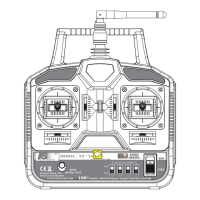
Transmitter Components:
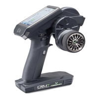
The transmitter features a standard pistol-grip design with several key controls:
- Antenna: For transmitting radio signals.
- Handle: Ergonomically designed for comfortable grip.
- Throttle/Brake Stick: Controls the forward/reverse movement and braking.
- Throttle/Brake Trim: Adjusts the neutral position of the throttle/brake.
- Steering Stick: Controls the left/right steering.
- Steering Trim: Adjusts the neutral position of the steering.
- Power Indicator Light: Shows the power status (red light or flashing indicates low battery).
- Power Switch: Turns the transmitter on/off.
- BIND Knob: Used for the binding process between the transmitter and receiver.
- Battery Box/Cover: Houses the 8 "AA" batteries required for power.
- Servo Reverser Switches: Allows reversing the direction of movement for Rudder (RUD), Throttle (THR), Elevator (ELE), and Aileron (AIL) channels.
- Range Test Button: For performing a range test.
- High/Mid/Low Switch: Likely for adjusting dual rates or travel limits.
Receiver Connections:
The 3-channel receiver provides connections for:
- Channel 1: Steering servo
- Channel 2: Speed controller
- Channel 3: Battery connection (especially for gas-powered models)
- BIND/VCC Port: Used for the binding process.
Binding (Matching) Process:
The system is factory-matched, but if a new receiver or transmitter is used, a binding process is required:
- Ensure the 2.4GHz transmitter has batteries installed and is switched off.
- Insert the matching lines into the "BIND/VCC" port of the receiver.
- Switch on the ESC or connect a receiver battery to channel 3. The red LED on the receiver will flash, indicating BIND mode.
- Press and hold the "BIND" button on the transmitter and then switch on the transmitter's power supply.
- Observe the receiver's LED. If it stops flashing, the binding is successful.
- Release the "BIND" button and remove the matching line.
- Test the servo operation. If it fails, repeat the process.
Switch On/Off Sequence:
- Switch On:
- Connect all servos.
- Switch on the transmitter.
- Switch on the ESC or power supply.
- The receiver LED should light solid.
- The system is ready for use.
- Switch Off:
- Cut off the ESC or receiver power supply first.
- Then, cut off the transmitter power supply.
- Warning: Reversing this sequence can lead to uncontrolled model movement and accidents.
Failsafe Function:
The Failsafe function is a crucial safety feature that protects the model in case of radio interference, low transmitter battery, or if the model goes out of range. In such situations, the system automatically switches the servo (typically the throttle) to a pre-set "brake" or "stop" position, preventing runaway models.
Failsafe Setup:
- Turn on the transmitter.
- Connect power to the receiver; the receiver's LED should be solid.
- Control the throttle trigger to the desired "brake" or "stop" position and hold it.
- Press the "set up" button on the receiver. The receiver's LED will flash for 3 seconds.
- The Failsafe setup is complete.
Failsafe Testing:
- Turn on the transmitter.
- Connect power to the receiver.
- Turn off the transmitter.
- The servo controlled by Failsafe should automatically move to the pre-set "brake" or "stop" position.
- If this sequence is followed and the servo responds as expected, the Failsafe setting is correct.
Important Safety Guidelines:
- Do not use the product in bad weather conditions (e.g., rain, thunderstorms) to ensure the safety of yourself and others.
- Before use, always verify that the servo movements correspond correctly with the joystick directions. Adjust if inconsistent.
- Always follow the correct power-on and power-off sequence (transmitter on first, receiver on second; receiver off first, transmitter off second) to prevent uncontrolled movements and accidents.
- This product is not suitable for children under 15 years of age.
Maintenance Features:
The manual emphasizes proper handling and storage of the device. Keeping the manual for future reference is recommended for troubleshooting. In case of persistent problems, users are advised to contact dealers or the service center at www.absima.com. The robust design with a black finish and durable components suggests a system built for regular use in RC environments. The battery box is easily accessible for battery replacement.