9 ALSV01B
Commissioning
Code Possible Settings
IMPORTANT
No. Name Default Selection
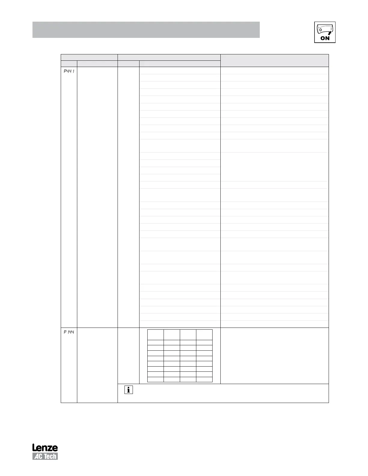
p441
Relay Output
TB-19, 20, 21
0 0 None Disables the output
1 Run Energizes when the drive is running
2 Reverse Energizes when reverse rotation is active
3 Fault De-energizes when the drive trips, or power is removed
4 Inverse Fault Energizes when the drive trips
5 Fault Lockout P110 = 3...6: De-energizes if all restart attempts fail
6 At Speed Energizes when output frequency = commanded frequency
7 Above Preset Speed #6 Energizes when output frequency > P136
8 Current Limit Energizes when motor current = P171
9 Follower Loss (4-20 mA) Energizes when 4-20 mA signal falls below 2 mA
10 Loss of Load Energizes when motor load drops below P145; Refer to
P146 also
11 Local Keypad Control Active
Energizes when the selected source is active for start
control
12 Terminal Strip Control Active
13 Remote Keypad Control Active
14 Network Control Active
15 Standard Reference Active Energizes when P101 reference is active
16 Auto Reference Active Energizes when Auto Reference is activated using TB-13
input; refer to P121...P124
17 Sleep Mode Active Refer to P240...P242
18 PID Feedback < Min. Alarm Energizes when PID feedback signal < P214
19 Inverse PID Feedback < Min. Alarm De-energizes when PID feedback signal < P214
20 PID Feedback > Max Alarm Energizes when PID feedback signal > P215
21 Inverse PID Feedback > Max Alarm De-energizes when PID feedback signal > P215
22 PID Feedback within
Min/Max Alarm range
Energizes when PID feedback signal is within the Min/Max
Alarm range; refer to P214, P215
23 PID Feedback outside
Min/Max Alarm range
Energizes when PID feedback signal is outside the Min/Max
Alarm range; refer to P214, P215
24 Reserved
25 Network Activated Requires 15HP (11kW) or higher drive.
No function for 0.33-10HP (0.25kW-7.5kW) drives.
26 Loss of 0-10V Input Energizes when 0-10V signal < P158
27 Sequencer Controlled State set in individual sequencer segments
28 Sequencer Active
29 Sequencer Suspended
30 Sequence Done End sequence
31 Output Frequency = 0.0Hz Output inactive
P144
Digital Output
Inversion
P144
Invert
P441
Invert
P142
Invert
P140
0 NO NO NO
1 NO NO YES
2 NO YES NO
3 NO YES YES
4 YES NO NO
5 YES NO YES
6 YES YES NO
7 YES YES YES
Used to invert the selections for P140, P441 (Relay Output)
and P142 (TB-14 Output).
EXAMPLE: When P140 = 6 (AT SPEED), the relay is
energized when output frequency = commanded
frequency. IF P144=1, 3, 5 or 7, then P140 is inverted
(INVERSE AT SPEED) and the relay is energized when the
output frequency does not equal the command frequency.
NOTE
Inverting P140, P142 or P441 when the parameter is set to NONE (0) will result in the output being
energized continuously.