EasyManua.ls Logo

Acclaim Lighting LFL2M - User Manual

Acclaim Lighting LFL2M
4 pages
Print Icon
To Next Page IconTo Next Page
Loading...
P: 866-845-5451 • F: 866-816-6165 • E: service@acclaim-lighting.com
Floodlight Installation and
Wiring Instructions
WARNING
: To avoid electrical shock. Do not at
tempt to install the fixture
in wet or rainy conditions. Always turn off electr
ical power at the circuit
breaker or by disconnecting the fuse.Only use bulbs in compliance with
manufactures specifications.
DO NOT ATTEMPT TO EXCEED MAXIMUM WATTAGE RATING.
TOOLS AND MATERIALS REQUIRED
Blade and or Phillips Head screw driver
Step Ladder(if needed)
Wiring supplires as required by electrical code:
Wire connectors
Electrical tape
UNPACK THE FIXTURE
Check the contents of the box.You should receive:
Outdoor fixture
Mounting Hardware package.
CAUTION
WARNING: Risk of fire.
Before installing your lighting fixture, thoroughly
review the section titled wiring connections.
If you do not have sufficient electrical wiring expe
rience, please refer to a do-it-yourself wiring
handbook or have your fixture installed
by a qualified licensed electrician.
All electrical connections must be
in accordance with local and Nationa
l Electrical Code(N
EC) standards.
If you are unfamiliar with proper electrical wiring conn
ections obtain the services
of a qualified electrician.
GENERAL
Remove the fixture and the mounting hardware packag
e from the box and make sure that no parts are missing by
referencing the illustration
s on the installation instructions.
To ensure success of the installa
tion, read these instru
ctions and review the diagrams thoroughly.
Save these instructions for future reference.
This fixture is intended to be mounted
to a 4”x4”x2-1/8” deep metal outlet box.
The building structure must di
rectly support the outlet box.
Before starting the installation, disconnect the power by turning off the circuit breaker or by removing the
fuse at the box. Turning the power off using the light
switch is not sufficient to
prevent electrical shock.
WIRING CONNECTIONS
Required supply circuit: 120V,60Hz.
Connect the white wire from the fixture to the white wire of the supply circuit.
Connect the black wire from th
e fixture to the black wire of the supply circuit.
Connect the green(or bare copper)colored wire to the grounding conductor of the supply circuit.
Use UL/CSA listed wire connectors suitable fo
r the size, type, and nu
mber or conductors.
No loose strands or loose connections should be present.Secure wire connectors with Use UL/CSA listed electrical tape.
LFL2M
1500 Cherokee Parkway, Suite 100, Acworth, GA 30102
Question and Answer IconNeed help?

Do you have a question about the Acclaim Lighting LFL2M and is the answer not in the manual?

Summary

Tools and Materials Required

Unpack the Fixture

Check the contents of the box for the outdoor fixture and mounting hardware package.

General Installation Steps

Wiring Connections

Motion Sensor Operation Modes

Mode Switch Summary

Overview of how to switch between AUTO and MANUAL modes using the light switch.

Installation Guide

Eave Mount Instructions

Specific steps for rotating the sensor head for proper operation when installing under an eave.

Wire the Light Control

Test and Adjustment

Sensor Aiming and Coverage

Adjusting sensor range, coverage angle, and aiming for optimal motion detection.

Specifications

Troubleshooting Guide

Overview

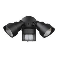
This document provides installation and operation instructions for the LFL2M Floodlight, which includes a motion sensor light control (models LFL2WHM/LFL2ABZM). The floodlight is designed for outdoor use and features motion detection, automatic shut-off, and a photocell to prevent activation during daylight hours.

General Installation Guidelines:

Before beginning installation, it is crucial to review all instructions and diagrams thoroughly. The floodlight is intended for mounting to a 4"x4"x2-1/8" deep metal outlet box, which must be directly supported by the building structure. To prevent electrical shock, always disconnect power at the circuit breaker or by removing the fuse before starting installation. Turning off the light switch alone is not sufficient.

Safety Warnings:

  • Electrical Shock: Do not attempt to install the fixture in wet or rainy conditions. Always turn off electrical power at the circuit breaker or by disconnecting the fuse.
  • Bulb Compliance: Only use bulbs that comply with the manufacturer's specifications.
  • Wattage Rating: Do not exceed the maximum wattage rating of the fixture.
  • Risk of Fire: Do not aim the floodlight heads at a combustible surface within 3 ft. (1 m).
  • Wiring Expertise: If you lack sufficient electrical wiring experience, consult a do-it-yourself wiring handbook or have the fixture installed by a qualified, licensed electrician. All electrical connections must adhere to local and National Electrical Code (NEC) standards.

Tools and Materials Required:

  • Blade and/or Phillips Head screwdriver
  • Step ladder (if needed)
  • Wiring supplies as required by electrical code
  • Wire connectors
  • Electrical tape

Unpacking the Fixture:

Upon opening the box, verify that all contents are present: the outdoor fixture and the mounting hardware package.

Wiring Connections:

The floodlight requires a 120V, 60Hz supply circuit.

  1. Connect the white wire from the fixture to the white wire of the supply circuit.
  2. Connect the black wire from the fixture to the black wire of the supply circuit.
  3. Connect the green (or bare copper) colored wire from the fixture to the grounding conductor of the supply circuit.
  4. Use UL/CSA listed wire connectors that are suitable for the size, type, and number of conductors.
  5. Ensure there are no loose strands or connections. Secure wire connectors with UL/CSA listed electrical tape.

Installing the Light Control:

  1. Remove the existing light fixture.
  2. Install the mounting strap using two screws that fit your junction box.
  3. Route the light control's wires through the large gasket holes.
  4. Twist the junction box wires and fixture wires together as shown in the diagrams, securing them with wire connectors.
  5. Align the light control cover plate and cover plate gasket. Secure them with the mounting bolt.
  6. Push the rubber plug firmly into place.
  7. If a wet location junction box was not used, caulk the wall plate mounting surface with silicone sealant.
  8. To avoid water damage and electrical shock, keep the floodlight heads' holders below horizontal.
  9. Adjust the heads by loosening the lock nuts, but do not rotate them more than 180° from the factory setting. When screwing in the heads, do not overtighten. Ensure the heads are at least 1" (25 mm) from the sensor and do not block its lens.

Motion Sensor Light Control Features:

The motion sensor light control automatically turns on lighting when motion is detected and turns it off after a set period. A photocell keeps the lighting off during daylight hours.

Requirements for the Motion Sensor:

  • The light control requires 120-volts AC.
  • If you intend to use Manual Mode, the control must be wired through a switch.
  • Some codes may require installation by a qualified electrician.
  • This product is designed for use with the enclosed gasket and with a junction box marked for use in wet locations.

Operation Modes:

The motion sensor light control offers three modes:

  • TEST Mode:

    • On-Time: 10 Seconds.
    • Works: Day and Night.
    • This mode is useful for initial setup and aiming the sensor.
    • When first turned on, wait approximately 40 seconds for the circuitry to calibrate.
    • Set the switch on the bottom of the sensor to TEST.
  • AUTO Mode:

    • On-Time: 1 or 5 Minutes.
    • Works: Night only.
    • The control will automatically turn on when motion is detected at night and turn off after the set duration.
    • Set the switch to 1 or 5 minutes.
  • MANUAL Mode:

    • On-Time: To Dawn (resets to Auto Mode at dawn).
    • Works: Night only.
    • Manual mode allows the light to stay on continuously through the night.
    • To toggle between AUTO and MANUAL MODE, flip the light switch off for one second, then back on. This action will switch the mode. Manual mode only works at night because daylight returns the sensor to AUTO.
    • Manual mode works only with the ON-TIME switch in the 1 or 5 position.
    • If you become confused when switching modes, turn the power off for one minute, then back on. After the calibration time, the control will revert to AUTO mode.

Installation for Best Performance:

For easy installation, select an existing light with a wall switch for replacement. For optimal performance, mount the fixture approximately 8 ft. (2.4m) above the ground. If the fixture is mounted higher than 8 ft. (2.4m), aiming the sensor down will reduce the coverage distance.

Eave Mount Specifics:

For under-eave installation, the sensor head must be rotated to ensure proper operation and to avoid electrical shock.

  1. Swing the sensor head towards the clamp screw joint.
  2. Rotate the sensor head clockwise 180° so the controls face down.
  3. If the sensor pops out of the ball joint, loosen the clamp screw, push the sensor back into the ball joint, and then tighten the clamp screw.

Test and Adjustment:

  1. Turn on the circuit breaker and light switch.
    • Note: The sensor has a 40-second warm-up period before it can detect motion. When first turned on, wait 1 minute.
  2. Set the RANGE control to the medium position (halfway between MIN and MAX), and the ON-TIME control to the TEST position.
  3. Loosen the clamp screw in the sensor ball joint and gently rotate the sensor.
  4. Walk through the coverage area, noting where the lights turn on (the LED will also flash several times when motion is detected). Move the sensor head up, down, or sideways to change the coverage area. Keep the sensor at least 1" (25 mm) away from the bulbs.
  5. Adjust the RANGE as needed. Setting the RANGE too high may increase false triggering.
  6. Secure the sensor head by tightening the clamp screw. Do not overtighten the screw.
  7. Set the amount of TIME you want the lights to stay on after motion is detected (1 or 5 minutes).

Avoiding False Triggers:

To prevent false triggering, avoid aiming the control at:

  • Objects that rapidly change temperature, such as heating vents and air conditioners.
  • Areas where pets or traffic may trigger the control.
  • Nearby large, light-colored objects that reflect light, which may trigger the shut-off feature.
  • Do not point other lights at the sensor.

Sensor Sensitivity:

The detector is less sensitive to motion coming directly at it. Aiming the sensor down provides short coverage, while aiming it higher provides long coverage.

Troubleshooting Guide:

This section helps diagnose and resolve common issues:

  • Lights will not come on:

    • Check if the light switch is off.
    • Verify if the fuse is blown or circuit breaker is off.
    • Confirm if daylight turn-off is in effect (recheck after dark).
    • For new installations, verify correct wiring.
    • Re-aim the light control to cover the desired area.
  • Lights come on in daylight:

    • The light control may be installed in a relatively dark location (this is normal operation).
    • The light control may be in TEST mode (set control switch to 1 or 5 minutes).
  • Lights come on for no apparent reason:

    • The light control may be sensing small animals or automobile traffic (re-aim light control).
    • The range may be set too high (reduce range).
    • The fixture may be operating normally under these conditions.
  • Lights stay on continuously:

    • A flood lamp may be positioned too close to the light control or pointed at nearby objects that cause heat to trigger the light control (reposition the flood lamp or nearby objects).
    • The light control may be picking up a heat source like an air vent, dryer vent, or brightly painted, heat-reflective surface (reduce range).
    • The light control may be in manual mode (switch light control to AUTO).
  • Lights flash on and off:

    • Heat or light from the flood lamp may be turning the light control on and off (reposition the flood lamp).
    • Heat being reflected from other objects may be turning the light control on and off (reposition light control).
    • The light control may be in TEST mode and warming up (flashing is normal under these conditions).
  • Lights flash once, then stay off in manual mode:

    • The light control is detecting its own lights (reposition the flood lamp to keep the area below the light control relatively dark).

This comprehensive guide ensures safe installation, optimal performance, and effective troubleshooting for your LFL2M Floodlight with motion sensor control.

Acclaim Lighting LFL2M Specifications

General IconGeneral
TypeLED Flood Light
IP RatingIP65
MaterialAluminum
Color Temperature5000K
VoltageAC100-277V
Beam Angle100°