Hardware and physical integration guideline A1 PCR sensors
Page 15 of 30
2024-02-07 © 2024 by Acconeer – All rights reserved
3.7 Radomes
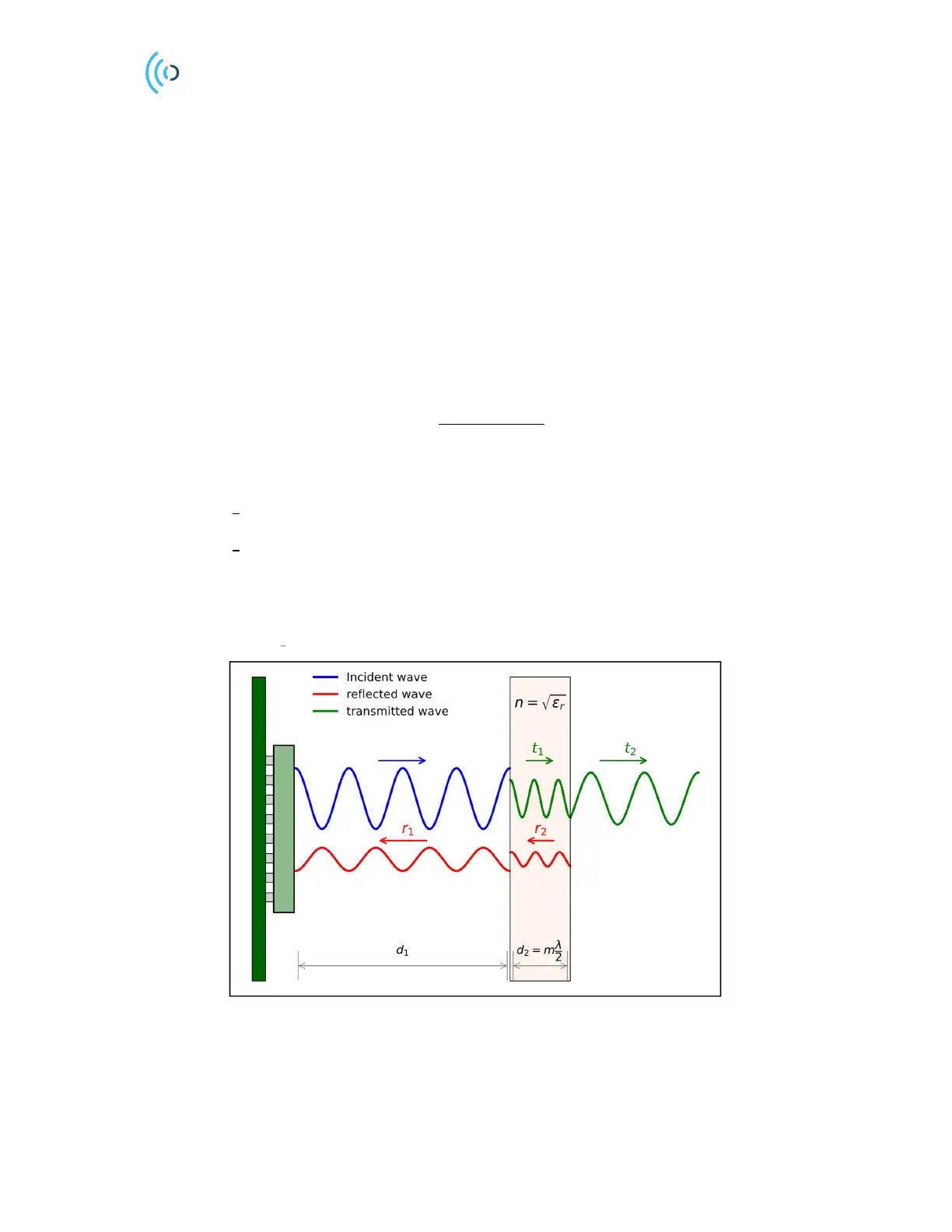
A radome is a dielectric layer that is transparent to the radar signal while protecting the radar from
mechanical impact and weather, see Figure 11. Often the product encapsulation can be made as a
radome without introducing additional costs. We will here see that by tuning the radome thickness and
distance, the radome can be made transparent to the radar.
3.7.1 Radome thickness
Let 𝑑
be the distance to the radome, 𝑑
the thickness, 𝑟
and 𝑟
the reflection coefficients and 𝑡
and
𝑡
the corresponding transmission coefficients, see Figure 11. As an incident wave hits the first
interface, a reflection 𝑟
and transmission 𝑡
happens. Notice that 𝑟
< 1 so that the reflected wave is
out of phase with the incident wave. At the second interface, another reflection (𝑟
) and transmission
takes places (𝑡
). With air on both sides of the dielectric, we note from Eq. (3) that 𝑟
=−𝑟
. The total
reflection coefficient Γ
then becomes [5]
Γ
=
𝑟
(1 − 𝑒
)
1 − 𝑟
𝑒
,
where 𝑘=2𝜋/𝜆 is the wave number in the material. Two important special cases follow:
For
we have
=1 or
(4)
For
we have
=-1 or
.
(5)
The optimum radome thickness, that is, the dielectric is perfectly reflectionless for thicknesses
equal to a multiple of half a wavelength. This can also be understood from that the round trip
of the wave inside the radome (
) introduces a 360-degree phase shift therefore cancelling out
Figure 11. Transmitted and reflected signals from a half wavelength radome. Secondary reflections have been omitted
for simplicity.
As an example, if the material relative permittivity is 𝜖
=2.6, the optimal radome thickness becomes
 Loading...