Hardware and physical integration guideline A1 PCR sensors
Page 16 of 30
© 2024 by Acconeer – All rights reserved 2024-02-07
𝑑=𝑚
𝜆
2
=𝑚
𝜆
2√𝜖
=𝑚
5
2√2.6
=𝑚∗ 1.55 mm
If the dielectric is an odd multiple of 𝜆/4, we encounter maximum reflection.
3.7.2 Radome distance
In addition to the radome thickness, the distance between the sensor and radome impacts. Depending
on the radome thickness and distance, the initial reflection from the radome will further cause multiple
reflections from the sensor, PCB and radome. This leads to a standing wave pattern where the
amplitude varies as a function of the radome distance. The amplitude variation will be a minimum if
the reflected wave from the radome is in-phase with the transmitted wave, that is, the optimum radome
distance is
𝑑
=𝑚
𝜆
2
,𝑚=1,2,3,…
This optimum distance is valid if the thickness of the radome is optimum as well. In the case when this
cannot be fulfilled, minimum insertion loss on the received signal is obtained when the distance to the
sensor satisfies the following criteria:
𝑚
𝜆
4
− 𝛿<𝑑
<𝑚
𝜆
4
+ 𝛿,𝑚=1,3,5,…
In order to have zero insertion loss, 𝛿 is determined to be 0.5 mm.
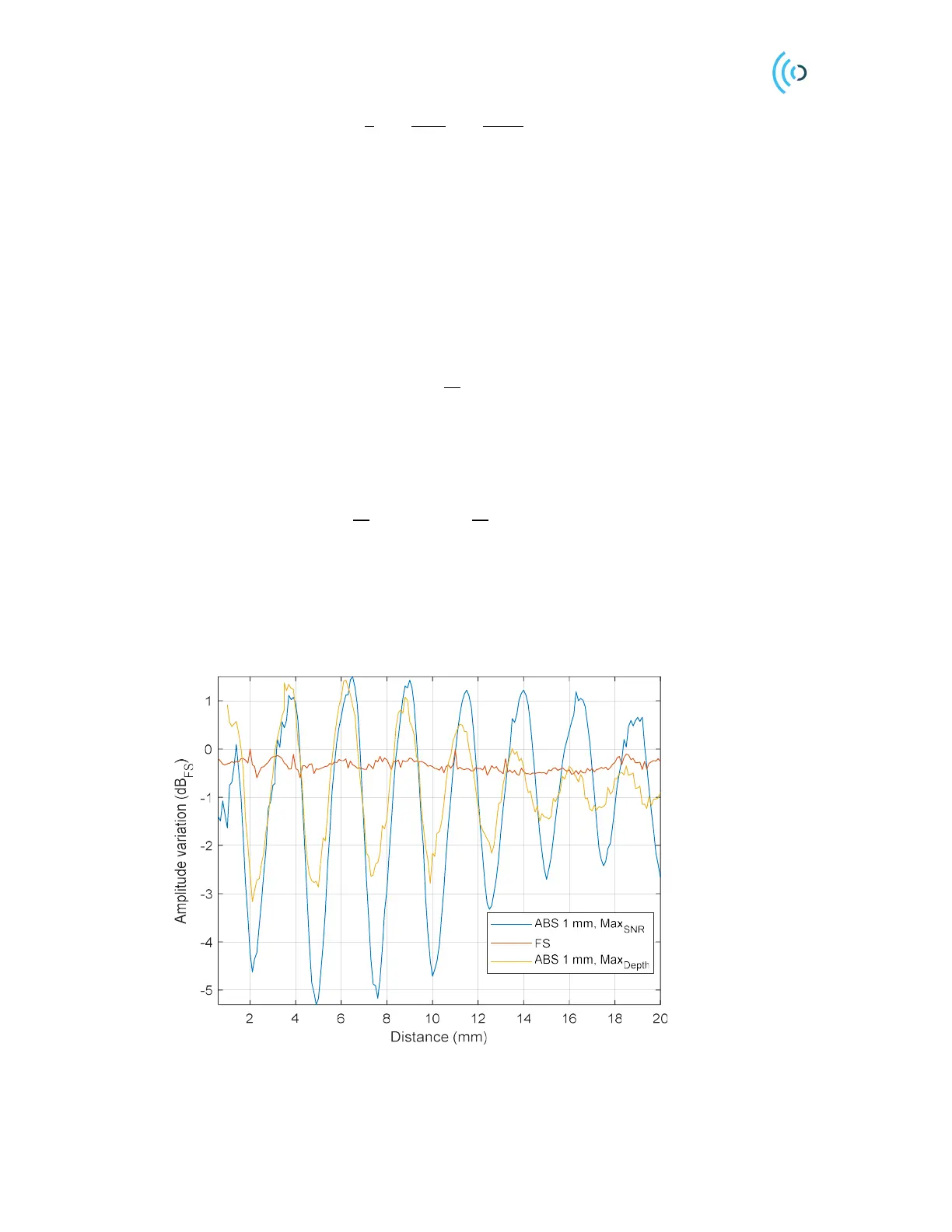
Figure 12 shows the amplitude variation as a function of distance d
1
with a 1 mm thick radome made of
ABS (𝜖
=2.6). When the distance d
2
gets larger than the pulse length, the standing wave disappears.
Figure 12. Measured reflected power from the target versus the 1 mm radome to sensor distance for two different
profiles. Amplitude is normalized by the free space amplitude for each profile. Amplitude variation is stated in one
direction (Tx or Rx side). For Radar loop Gain (RLG) the values will be doubled.
 Loading...