Hardware and physical integration guideline A1 PCR sensors
Page 17 of 30
2024-02-07 © 2024 by Acconeer – All rights reserved
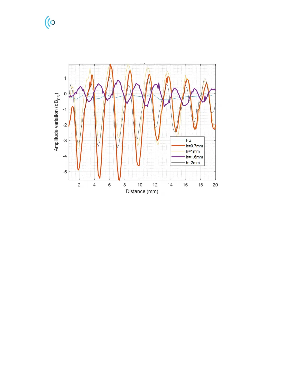
Figure 13 shows the measured amplitude variation of the reflected wave from a radar target when the
distance between the sensor and the radome is varied for different radome thicknesses. A radome
thickness of λ/2 = 1.6 mm results in the smallest amplitude variation whereas as thickness of λ/4 = 0.7
mm gives the largest amplitude variation.
Figure 13. Impact of the thickness of the radome (made of ABS) on the reflected amplitude variation. The amplitude
is normalized to maximum value of the free space (FS). Amplitude variation is stated in one direction (Tx or Rx side).
For Radar Loop Gain (RLG) the values will be doubled.
If absolute measurements are required for a certain use case, it is advised that an additional offset is
added to the distance measurement. The reason for this offset is that the propagation delay caused by
the radome must be compensated. This additional offset is obtained by making reference
measurements, and it will also allow you to place the reference plane at the desired location for your
product. For multi-layer radome optimization, readers can find more information in [5].
 Loading...