Hardware and physical integration guideline A1 PCR sensors
Page 26 of 30
© 2024 by Acconeer – All rights reserved 2024-02-07
4.4.1 Focal distance tuning
The focal distance F is an input parameter for all lens designs provided here. However, the optimal
focal distance may need to be slightly adjusted such that the reflection from the lens is simultaneously
minimized. In addition, other effects can impact the focal point, such as material permittivity being
slightly off, impact of lens housing, radomes and other nearby mechanics.
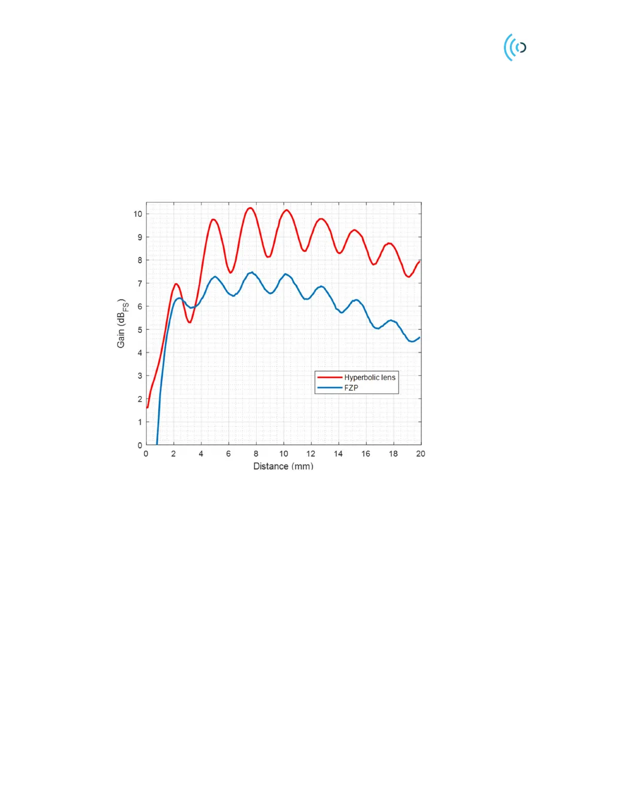
Figure 24 shows the gain variation of the integrated lens with the radome with respect to the free space
scenario for the XM112 module. The maximum gain happens at 7.5 mm distance for both lenses.
Other maxima happen every half-a-wavelength (2.5 mm).
Figure 24. Gain variation of the lens versus the distance to the XM112 radome. The amplitude is normalized to free
space (FS). Gain is stated in one direction (Tx or Rx side). For Radar Loop Gain (RLG) the values will be doubled.
4.4.2 Customized lenses
The lens design equations provided here are based on ray optics and may not be adequate in more
challenging applications, especially when the lens diameter is small. With a full wave EM solver,
Acconeer can construct optimized lenses for maximizing the gain, minimizing side lobes or
customizing radiation patterns. The impact of lens housings, nearby mechanics and the PCB can also
be simulated. Acconeer provides a design service for this, visit the Acconeer Developer page for
details [1].
 Loading...