Hardware and physical integration guideline A1 PCR sensors
Page 25 of 30
2024-02-07 © 2024 by Acconeer – All rights reserved
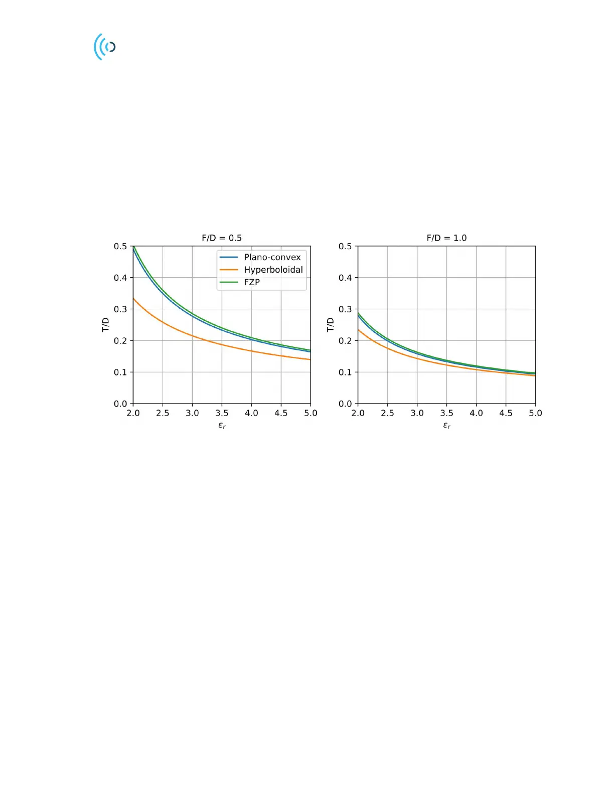
4.3.2 Lens thickness comparison
For mass production, injection molding is usually cost effective but producing thick lenses can be
challenging as sink marks and other deformations can occur. It is therefore of interest to find lens
designs which are as thin as possible. In Figure 23 we have compared the lens thickness to diameter
ratio (T/D) as a function of ε
r
. Common thermoplastics have ε
r
in the range 2-4 and the hyperboloidal
lens is the thinnest lens. To further obtain thinner lenses we can increase the F/D ratio, but this may
also increase the side lobe level due to spillover radiation from the sensor, especially for small
diameter lenses.
Smaller F/D ratios can be chosen than 0.5 with the cost of increased thickness. For short focal distance
lenses, the FZP lens is a good option as its thickness only depend on ε
r
.
Figure 23. Lens thickness comparison.
4.4 Lens design guidelines and prototyping
In general, multiple design aspects must be considered when choosing a lens type. Whenever possible,
the lens can be made as a part of the outer enclosure and therefore avoid the need for an additional
radome. For applications requiring a flat outer surface, convex-planar or FZP lenses are good choices.
Outdoor applications may need to consider rain or ice buildup and here the lens outer surface is chosen
to minimize this impact. For example, an upwards pointing convex surface would collect less rain.
Manufacturing lenses by injection molding may pose limitations on the lens maximum thickness. For
the refracting type lenses, thin lenses are obtained by choosing a high F/D ratio and higher permittivity
materials. On the other hand, higher F/D ratios occupy more space as well as increased spillover
energy which in turn leads to larger side lobes. For the plano-convex and convex-planar lenses, it is
therefore recommended to keep 0.4 < F/D < 0.8. Lens designs with F/D outside this range is certainly
possible, but with additional loss in directivity and increased side lobes. When large diameter lenses
are required, FZP type lenses should be considered as its thickness only depend on the permittivity and
are thus generally thinner than refracting type lenses.
For maximum gain and low side lobe level, it is important to also follow the PCB ground plane
guidelines in Chapter 3.3.
 Loading...