Hardware and physical integration guideline A1 PCR sensors
Page 6 of 30
© 2024 by Acconeer – All rights reserved 2024-02-07
2 Electrical integration
2.1 A111 Power
The A111 radar sensor is powered by 1.8 V and all the control signals, and the SPI interface are 1.8 V
pins. It must therefore be ensured that all host MCU pins connected to the A111 are at 1.8 V. If this is
not the case, level-shifters must be used in between the A111 and the host MCU.
As mentioned in the power consumption summary of the A111 datasheet, the A111 typically
consumes 66 µA when the ENABLE pin is set low. If the leakage current is to be even further
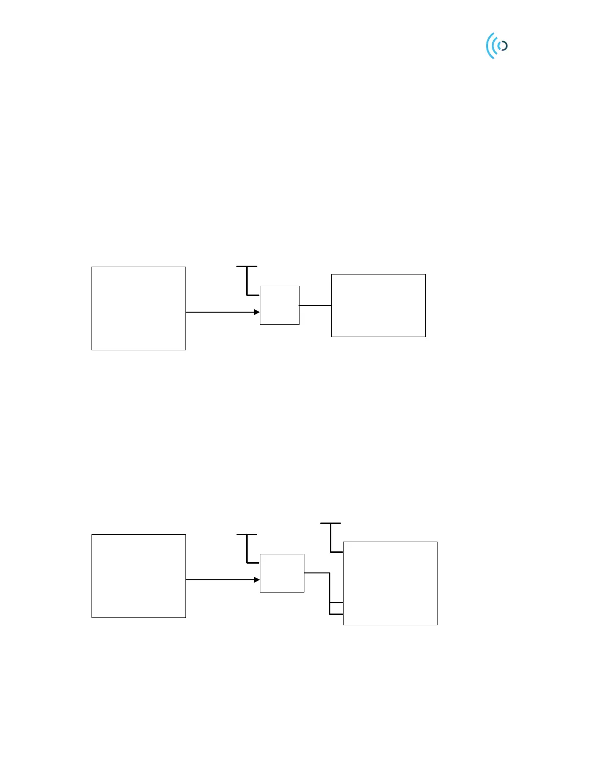
reduced, the power to the A111 must be switched off. It can be achieved either by using a low-leakage
power regulator with an enable/disable function (if 1.8 V is not available in the system) or a low-
leakage power switch in between the two 1.8 V domains. In both cases, a control signal,
PMU_ENABLE, is needed. See Figure 2 for details.
Host A111
VIN
PMU_ENABLE
PMU
1.8V
Figure 1. Block diagram of how to connect a Power Management Unit for controlling the 1.8 V to the A111.
If the power to the A111 is switched off in between sweeps it is important that the control signals and
SPI interface are pulled low during this time, otherwise reverse leakage will occur via the ESD diodes
in the A111. If it is not possible to set the SPI interface in such a state (either via SW or by configuring
any level-shifters that might be used in the design), the problem can be solved by adding a power
switch only to VIO1 and VIO2. This way the leakage will be significantly lower than 66 µA, but the
control signals and SPI interface of A111 will still be supplied by 1.8 V and thus no reverse leakage
will occur. See Figure 2 for details. The Acconeer High Performance Module shows how to integrate a
power switch into the design, refer to the XM112 datasheet, available on the Acconeer Developer page
[1].
A111
Host
1.8V
PS_ENABLE
POWER
SWITCH
VIO3
VIO2
VIO1
1.8V
1.8V_SW
Figure 2. An example of how to connect a power switch to reduce the leakage current when A111 is powered off.
2.2 A121 Power
The A121 radar sensor needs 1.8 V input voltage to the RX, TX and VDIG power domains. The A121
VIO power domain can be powered by either 1.8 V or 3.3 V. To avoid stressing the A121 and to
 Loading...