ACCUPHASE LABORATORY, INC.
YOKOHAMA, JAPAN
820-3287-00 (B1) Printed in JapanF131.1X
INSTRUCTION MANUAL
Analog Disc Input Board
AD-30
Thank you for your purchase of the AD-30 analog-disc input board. This optional board
enables playback of analog discs. The board installs into an option slot on the rear of your
supporting Accuphase device.
Note that usage procedures vary according to the device. Please be sure to read your
device’s documentation before starting use.
Using the AD-30
How to Install
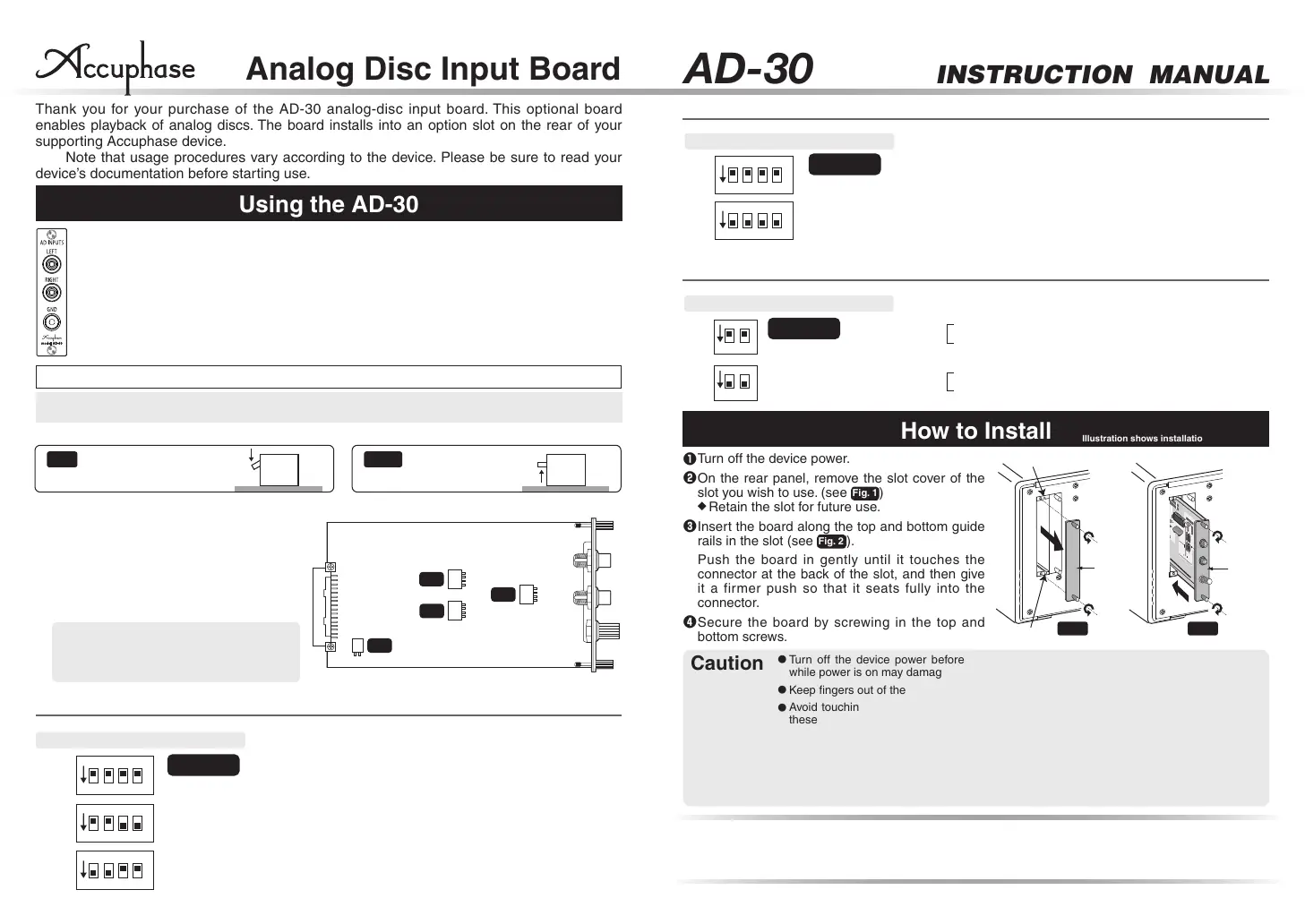
Illustration shows installation on the E-460.
❶
Turn off the device power.
❷
On the rear panel, remove the slot cover of the
slot you wish to use. (see
Fig. 1
)
◆
Retain the slot for future use.
❸
Insert the board along the top and bottom guide
rails in the slot (see
Fig. 2
).
Push the board in gently until it touches the
connector at the back of the slot, and then give
it a firmer push so that it seats fully into the
connector.
❹
Secure the board by screwing in the top and
bottom screws.
●
Turn off the device power before installing or removing option boards. Installing a board
while power is on may damage the equipment.
●
Keep fingers out of the opened slot. Do not place anything other than the board into the slot.
●
Avoid touching the board’s soldered areas, connector contacts, and components. Touching
these areas may damage the circuitry or the contact. Hold the board by the edges or along
its panel.
●
Tightly screw in the two screws all the way (by hand). If screws are loose, terminals may
separate from ground, resulting in poor contact or equipment damage.
●
Do not use electrical contact enhancers or conductivity agents on inputs and cable
connectors. The warranty does not cover damage caused by these materials.
Caution
*
In components with two slots, two boards can be installed.
*
The S1 setting affects both the left and right channels.
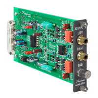
LEFT, RIGHT analog record player input jacks
Connect the output cable from the analog record player to these jacks.
GND terminal
Connect the ground cable that emerges from the analog record player to this terminal.
❶
S1: MC LOAD
-
MC input impedance selector
As a general guideline, set this switch as follows :
For MC cartridges with internal impedance of 20 ohms or more :
100 ohm or 300 ohm position
For MC cartridges with internal impedance of less than 20 ohms :
30 ohm or 100 ohm position
Generally, the input impedance setting should be about 2 to 3
times the rated cartridge impedance.
However, since the requirements of some cartridges may vary,
the final setting should be determined by ear.
This filter has a cut-off frequency of 25 Hz and a steep
attenuation slope of -12 dB/octave. lt cuts off unwanted subsonic
signal components without affecting the audible range.
MM: Use this position for moving magnet cartridges with high output
Gain: 40dB
Input Impedance : 47 kohms
MC: Use this position for moving coil cartridges with low output
Gain : 66dB
Input Impedance : As selected with S1
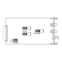
DIP switches S1, S2, S3, S4
Set these switches to the required positions before inserting the board.
❶
S1 : MC LOAD
MC input impedance selector:
30/100/300 ohms
❷
S2, S3 : FILTER
Subsonic filter on/off
❸
S4 : MC/MM selection
If the component where the board is installed
has an MC/MM selector on the front panel,
there is no need to set the S4 switch.
S4
AD-30 component side
(location of switches S1 - S4)
S3
S2
FILTER
S1
MC LOAD
MC/MM
❷
S2, S3: FILTER
-
Subsonic filter on/off
❸
S4: MC/MM
-
Equalizer gain selection
ON OFF
Push the bit down until
it stops.
Push the bit up until
it stops in horizontal
position.
(Illustration shows side view of switch.)
Note: Use a sharp pointed object to move the switch levers and make sure that the levers are set fully to one
side. If a lever is set only half-way, correct operation is not possible.
To ensure expected performance, push each switch bit fully into the appropriate position using a thin-tipped object.
1, 2, 3, 4 : OFF
3, 4 : OFF
1, 2 : ON
3, 4 : ON
1, 2 : OFF
300Ω
30Ω
100Ω
1 2 3
4
ON
1 2 3
4
ON
1 2 3
4
ON
(Illustration shows front view of switch.)
Factory default
setting
724-0019-00
724-0020-00
TOSHIBA
74HCTO
NFV510
20MHz0.24
Guide rail
Guide rail
Fig. 1 Fig. 2
Sub-
panel
Option
board
1, 2, 3, 4 : OFF
1, 2, 3, 4 : ON
OFF
ON
1 2 3
4
ON
1 2 3
4
ON
(Illustration shows front view of switch.)
Factory default
setting
1, 2 : OFF
1, 2 : ON
MM
MC
1
ON
2
1
ON
2
(Illustration shows front view of switch.)
Factory default
setting
*
Be sure to set both the S2 and S3 switches to the same position.
*
The S4 setting affects both the left and right channels.
 Loading...