EasyManua.ls Logo

Accuphase AD-50 - User Manual

Accuphase AD-50
2 pages
Print Icon
To Next Page IconTo Next Page
Loading...
使用方法
付け方法
ナロAD-50
ション ション
ーの再生使用い。
使用方法増設機器使用前各機器の取扱説明書
参照い。
取扱説明書
820-3317-00 (B1) Printed in JapanJ171.3X
ナロク入
AD-50
ーズ株式会社
225-8508 横浜市青葉区新石川2-14-10
TEL045(901)2771(代
増設機器の電源
ネルのサネル
。(
図1
参照)
※外保管い。
ン用のガに沿
ション
図2
ーに当
ら、にな
し込
上下の確実固定
ボーを抜き差ず増設る機器の電源を切る。
電源故障の原因ます
スロト内部に手などを入れない(スロト内部に、オプシド以外は入れないで
。)
品やハンダ、ターの接点部分を手で触ない。手で触接触不良や回路が故障す原因となるがあ
す。を持つ場合にはト板の外周やパネル部を持さい。
オボーの取付けネジは手で完全に締める締めつけが不完全で端子がグラドから浮いて接
触不良故障の原因なるがあます
入力端子やコネターな接点復活剤や導電剤は絶対使用ない。これらの要因る不具合は保証対象外
なりま
注意
LEFT, RIGHTアナレーヤー入力端子
   アレーヤーの出力ケーブルを接続す。
GNDアース端子
   アレーヤーの出力ケーブ一緒に出ていアース線を接続す。
S1 MC/MM
イコライゲイ
一般的は、MCカージの内部
20Ω以上100Ωは300Ωに設定
20Ω以下30Ωは100Ωに設定
ジの内部ピースの2~3倍以上
目安ますが、実際に試聴て良い音質の得
インピーダンスを決定ださい
ルタ超低域25Hz以下12dB/
octaveの減衰特性でカ超低域ズが
可聴帯域内へ悪影響をよぼ防ぎ
コーに大きな反があ超低域の
よりァーたりするとき
変有効です。
MM高出力電圧のMM型カのポす。
ン 40dB
入力イピース47kΩ
MC出力電圧が低いMC型のジのンです。
ン 66dB
入力イピースS3で切替え
S1, S2, S3 プスチの設定…挿入前に設定ます。
注意チの各キーは先の細いもので完全ださい。指定以外の設定では所定の特性を得られん。
S1 MC/MM
コライザーゲインの切
S2 SUBSONIC FILTER
ターのON/OFF
S3 MC IMPEDANCE
MCの入力インピーダスの選択
30/100/300Ω
増設する機器のパネル面に「MC/MM切替機
能」がある場合、パネル面の切替えが優先さ
ためボード上のS1の設定は必要あせん。
S1
AD-50
部品面
(S1~S3位置す。
S3
S2
SUBSONIC
FILTER
MC
IMPEDANCE
MC/MM
S2 SUBSONIC FILTER サブソニルターのON/OFF
❸S3 MC IMPEDANCE MCの入力インピーダンスの選択
1, 2, 3, 4 : OFF
3, 4 : ON
1, 2 : OFF
1, 2 : ON
3, 4 : OFF
300Ω
30Ω
100Ω
出荷位
1 2 3
4
ON
1 2 3
4
ON
1 2 3
4
ON
チを正面から見た図を示てい
1, 2 : OFF
1, 2 : ON
MM
MC
出荷位
1
ON
2
1
ON
2
チを正面か見た図を示してい
ON OFF
キーを止まるま
げる
キーを止まるま
げてにする
チは横から見た図を示ています。
お願い
品に対すお問い合わは異常が認め
の当社製品取扱店当社品質
保証部へ連絡い。
客様付属
1, 2, 3, 4, 5, 6 : OFF
1, 2, 3, 4, 5, 6 : ON
OFF
ON
出荷位
1 2 3
4
ON
1 2 3
56
56
4
ON
チを正面から見た図を示てい
イラトは E-650 です。
図1 図2
イド
イド
Question and Answer IconNeed help?

Do you have a question about the Accuphase AD-50 and is the answer not in the manual?

Summary

Using the AD-50 Analog Disc Input Board

Analog Input and Ground Connections

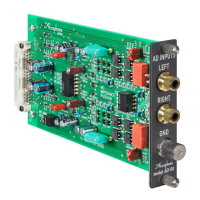
Connects analog player output cables and ground wire to the unit's jacks.

DIP Switch Settings Overview

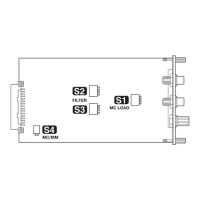
Details settings for S1 (MC/MM gain), S2 (Subsonic Filter), and S3 (MC Impedance).

AD-50 Installation Guide

Installation Procedure

Step-by-step instructions for physically installing the option board into the device.

Installation Safety Precautions

Critical warnings regarding power, handling, and component contact during installation.

Overview

The Accuphase AD-50 Analog Disc Input Board is an optional component designed to enhance your audio system by enabling the connection and playback of analog disc players. This board is installed into a dedicated slot on the rear panel of a compatible Accuphase device. Before installation, it is crucial to consult the manual of your Accuphase device, as operation may vary depending on the specific model.

Function Description

The AD-50 board provides input terminals for analog disc players, allowing you to connect both the left and right output cables from your turntable. It also includes a GND (ground) terminal for connecting the ground wire from your analog record player, which helps to minimize hum and noise.

The board features three DIP switches (S1, S2, S3) that must be configured before installation. These switches control various aspects of the board's operation:

  • S1: MC/MM Equalizer Gain Switch: This switch determines the equalizer gain setting for either Moving Magnet (MM) or Moving Coil (MC) cartridges.

    • MM (Moving Magnet): This position is for high-output voltage MM cartridges. It provides a gain of 40 dB and an input impedance of 47 kilohms.
    • MC (Moving Coil): This position is for low-output voltage MC cartridges. It provides a gain of 66 dB, and the input impedance is further determined by the S3 switch setting.
    • Note: If your Accuphase device has an MC/MM switch on its front panel, that panel setting takes precedence over the S1 setting on the board.
  • S2: Subsonic Filter ON/OFF: This switch activates or deactivates the subsonic filter.

    • When ON, this low-cut filter has a cutoff frequency of 25 Hz and a steep attenuation curve (-12 dB/octave). Its primary purpose is to filter out very low-frequency noise that could negatively impact audible ranges. This is particularly effective for reducing rumble noise from warped records and preventing woofers from "bottoming out" due to excessive low-frequency vibrations.
  • S3: MC Impedance Selection: This switch allows you to select the input impedance for MC cartridges.

    • The available impedance settings are 30, 100, and 300 ohms.
    • Generally, for MC cartridges with an internal impedance of 20 ohms or higher, you would set this to 100 or 300 ohms. For cartridges with an internal impedance below 20 ohms, settings of 30 or 100 ohms are typically recommended.
    • As a guideline, the impedance setting should ideally be about 2 to 3 times the cartridge's internal impedance. However, it is strongly recommended to experiment by listening to determine the setting that yields the best sound quality for your specific cartridge.

Usage Features

The AD-50 board is designed for straightforward integration into your Accuphase system.

  • Pre-installation Configuration: Before physically installing the board, ensure all DIP switches (S1, S2, S3) are correctly set according to your cartridge type and desired filter/impedance settings. Use a pointed object to firmly set the switch bits. Incorrectly set bits may prevent the board from functioning properly.
  • Easy Installation: The board slides into a designated slot on the rear panel of your Accuphase device, guided by upper and lower rails. Once it reaches the internal connectors, a gentle push will snap it into place, making the board flush with the panel. It is then secured with two screws at the top and bottom.
  • Optimized Playback: By correctly configuring the MC/MM gain, subsonic filter, and MC impedance, the AD-50 helps to optimize the playback of your analog records, ensuring accurate signal amplification and minimizing unwanted noise.

Maintenance Features

Proper handling and installation are key to the longevity and performance of the AD-50 board.

  • Power Off During Installation/Removal: Always turn off the power of your Accuphase device before installing or removing the AD-50 board. Installing or removing the board while the power is on can cause damage to the equipment.
  • Careful Handling: When handling the board, avoid touching the soldered areas, connector contacts, and components, as this can lead to contact issues or circuit damage. Always hold the board by its edges or along its panel.
  • Secure Fastening: Ensure the two screws used to secure the board are tightened all the way by hand. Loose screws can cause terminals to separate from the ground, resulting in poor contact or equipment damage.
  • Avoid Slot Contamination: Keep fingers and other objects out of the opened slot. Only the AD-50 board should be inserted into this slot.
  • No Contact Enhancers: Do not use electrical contact enhancers or conductivity agents on the input jacks or connectors. These substances can cause aging in resin parts and lead to damage over time.
  • Sub-panel Retention: When removing the sub-panel from the slot on your Accuphase device, be sure to retain it for future use.

By following these guidelines, you can ensure the AD-50 Analog Disc Input Board provides reliable and high-quality analog playback for many years. For any inquiries or issues, contact your Accuphase product dealer or the Accuphase quality assurance department.

Accuphase AD-50 Specifications

General IconGeneral
Sampling Rate44.1 kHz
Bit Depth16 bits
Input ConnectorsRCA
Output ConnectorsRCA, XLR
THD0.003%
Sampling Frequency44.1 kHz

Related product manuals