Optical Drive, I/O Expansion Bays, Hotswap HDD bays (optional)
Location: The optical drive, I/O expansion, and Hotswap HDD bays are optional add ons for this
model. The optical drive, I/O expansion, and Hotswap HDD, if applicable, are located in one of
the front drive bays of the chassis.
Type and number of fastenings: Four (4) Phillips Screws.
Tools required: Phillips Screwdriver.
Procedure:
Step 1: Ensure the computer is off, unplugged, and any potential energy is dissipated.
Step 2: Remove the side panel from the chassis as indicated in the “Chassis Cover” section of this
manual. For removal of the optical drive, both chassis covers will need to be removed. The
process is the same for both sides.
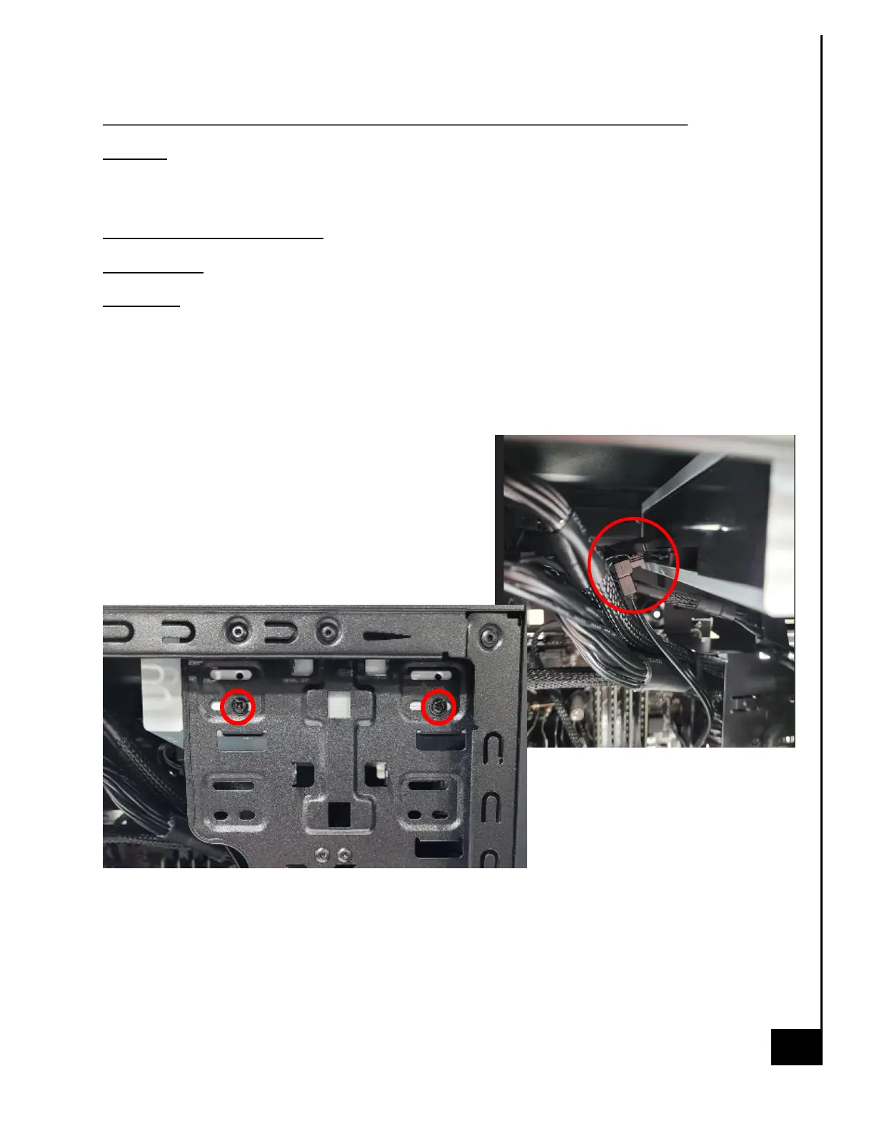
Step 3: Located along the front side of the chassis in
the mounting bays, are all of the add on drive bay
options, the add on options are generally mounted
with (4) Phillips screws, (2) on either side of the chassis.
Step 4: Disconnect SATA power and data cables from
all optional bays, as applicable.
Step 5: Remove 1-2 phillips screws on the internal side of the case