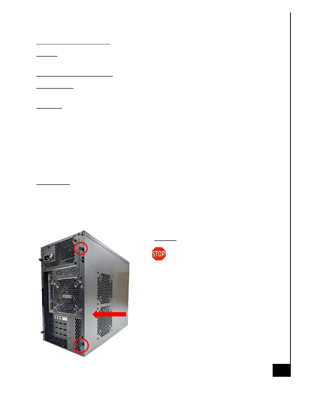
Chassis Cover Removal
Location: In order to access the internal components of your system, you will need to remove the
left cover of the chassis.
Type and number of fastenings: Two thumb screws
Tools required: None, thumb screws are intended to be unfastened with your thumb and
forefinger.
Procedure:
Step 1: Ensure the desktop is off, unplugged, and any potential energy is dissipated.
Step 2: Unfasten the (2) thumb screws on the left side rear, top and bottom, at the rear of the
chassis.
Step 3: Once removed, slide the chassis side panel parallel to the chassis towards the rear, this
will disengage the various tabs that are holding the panel to the chassis.
Step 4: This is the same process for the opposite side panel
Reinstallation
Step 5: To reinstall the panels lay them against the side of the case and gently slide them along
the perforations ensuring the tabs catch in the proper channels.
Step 6: Reinsert the thumb screws and tighten until firm.
Disposal:
Selective Treatment/Special Handling Per
Annex VII, Directive 2012/19/EU: None