-3-
598-1224-00
8. Route wires through wire entrance hole in new chime base.
9. Mount chime base to wall using screws and anchors provided.
(Drill 7/32" diameter pilot hole for wall anchors.)
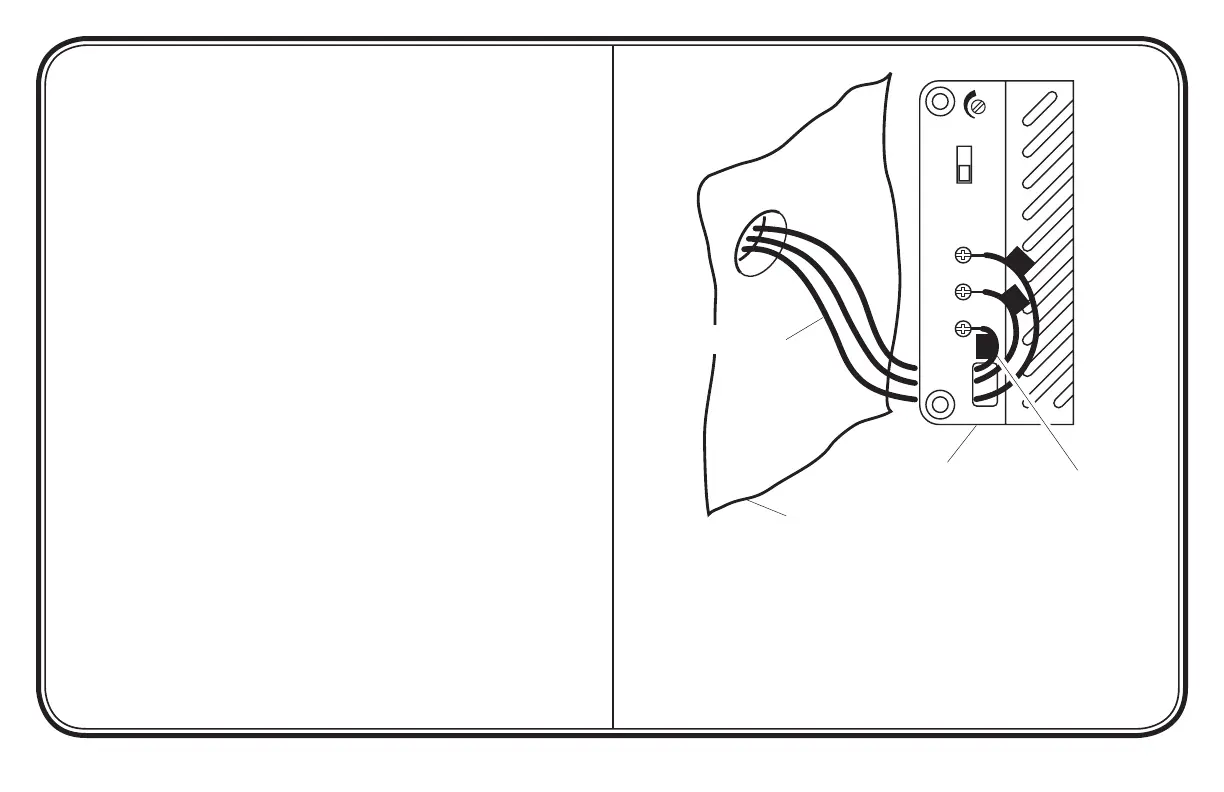
10. Connect wire “F” to screw terminal marked “FRONT”. Connect
wire “T” to screw terminal marked “TRANS”. Connect wire
“R” to screw terminal marked “REAR”* (See Figure 2).
11. Install chime cover (see page 4).
12. Connect diode to front push button (see page 5).
*Note: Some installations may not include rear door push button.
Figure 2 - Electronic Chime Wiring
(TR-0070-BX Base Shown)
FRONT
VOLUME
FRONT TUNE
A
B
TRANS
REAR
F
R
T
Existing Chime Wires
Wall
Replacement
Chime Base
Rear Door Push Button
(if Applicable)