Home
Acer
Monitor
AL1714
Service Guide
Page 21
Acer AL1714 - Page 21
48 pages
Manual
To Next Page
To Next Page
To Previous Page
To Previous Page
Loading...
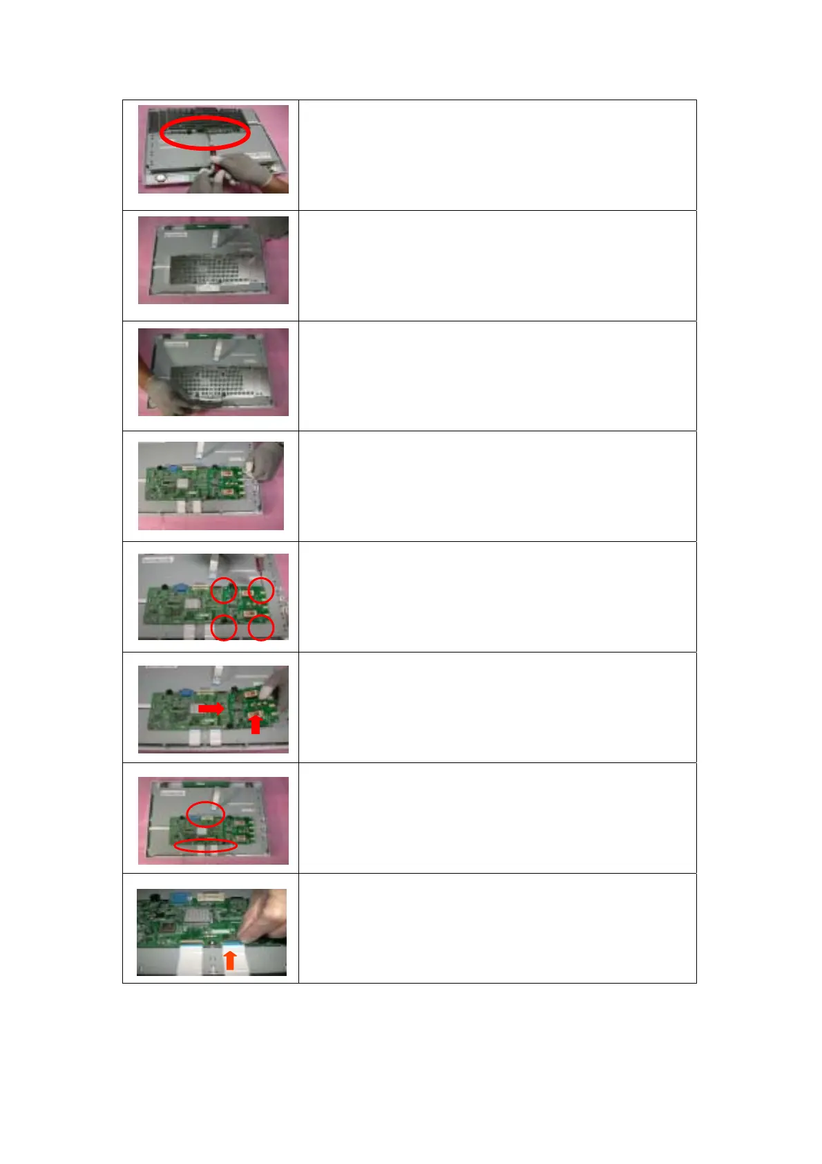
Loose an
d remov
e 4 scr
ews
Loose an
d remov
e 5 scr
ews
Remo
ve the Cover of
X-PCB
Remove 4
pieces o
f Backlig
ht wires.
Loose an
d remov
e 4 scr
ews
Remove Pow
er PCBA
Remove 3
pieces of FFC
from AD PCBA
Open the
f
ixed cov
er at
AD
21
20
22
Table of Contents
Main Page
Default Chapter
7
Table of Contents
7
Chapter 1 Monitor Features
8
Test Conditions
8
Features
8
Optical Specifications
9
LCD Panel Specification
11
Connector Pin Assignment
12
Chapter 2 OPERATING INSTRUCTIONS
14
Function Name
14
OSD Menu Description
16
OSD Operation
17
OSD Function Definition
18
Plug and Play
19
Power Saver
19
Chapter 3 Machine Disassembly and Assembly
20
Machine Disassembly
20
Machine Assembly
23
Chapter 4 Troubleshooting
26
Abnormal Display Troubleshooting
26
Abnormal (On/Off, LCD Display, K/B) Troubleshooting
28
Abnormal (BIOS, OSD, Other Display) Troubleshooting
29
Audio Abnormal
30
Chapter 5 Connector Information
31
Function Block Diagram
31
Connector Location
32
Main Board Pin Assignment Introduction
33
Chapter 6 FRU
38
Chapter 7 Schematic Diagram
41
Other manuals for Acer AL1714
User Manual
9 pages
Related product manuals
Acer AL1715
75 pages
Acer AL1716
20 pages
Acer AL1717
10 pages
Acer AL1706
10 pages
Acer AL1751
20 pages
Acer AL1916
67 pages
Acer AL1906
47 pages
Acer AL1914
86 pages
Acer AL1516
10 pages
Acer AL1521
50 pages
Acer AL1917W
44 pages
Acer AL1516W
41 pages