34
Remove the ribbon cable between the MSP-FET430UIF and the base board. Connect the NVIDIA supplied ribbon
cable that fits the MSP-FET430UIF to the MSP-FET430UIF end. Connect the other side of the cable as shown in
the picture above. Find the pin1 marker on the cable(it is indicated by a black arrow in the plastic in the header-this
is not very visible and can usually only be seen with extra lighting under a magnifier. Make sure that pin1 of the
ribbon cable header is connected to pin1 of the board header(indicated by a white arrow on the board-it is the pin
on the header that is closest to the SO-DIMM connector)
3.2.3 Starting the Software and Flashing the New Code
The steps to start the software and flash the code are the same as those described above for the flashing of the
base board micro-controller.
Now click the “Open code file” button, and browse to the “P2324_OEM_1_12.txt” file and select it. Once that file is
selected through the “Open Code File”button, click the “AUTO PROG” button to download and flash the code into
the micro-controller. Once again, you may have to power cycle the board in order to reset and restart all micro
controllers correctly.
4. G-SYNC module FW update
4.1 G-SYNC module FW update
This chapter describes how to flash Bitstream,BitmapsFiles(.bin),OSD control FW(.elf) and Panel profiles into
G-SYNC module.
4.2 Required Hardware
G-SYNC monitor with power supply
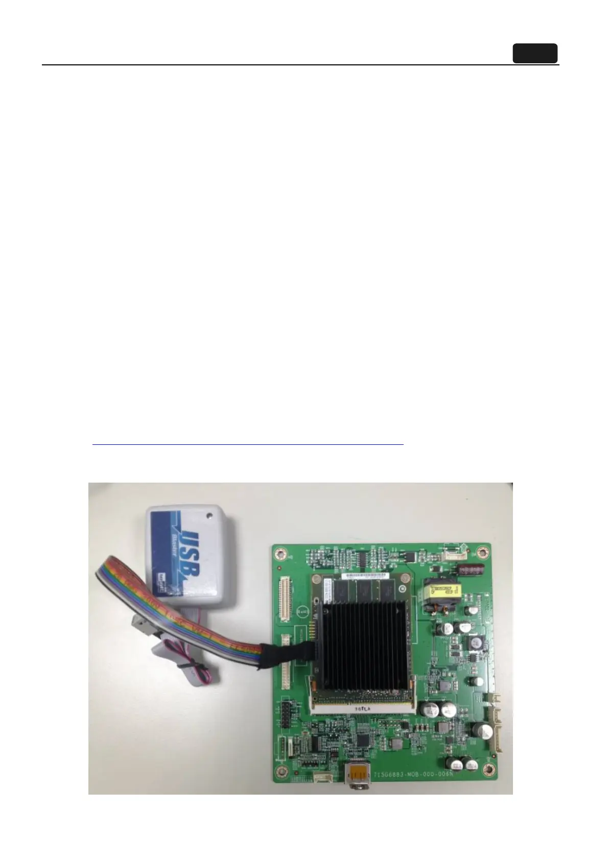
USB blaster
To download the program code into the FPGA, we use the Terasic USB Blaster:
http://www.terasic.com.tw/cgi-bin/page/archive.pl?Language=English
The USB port of the blaster is connected to the development computer, and the header cable is
connected to the header on the monitor.
 Loading...