EasyManua.ls Logo

ACERBIS TENERE 700 User Manual

ACERBIS TENERE 700
3 pages
To Next Page IconTo Next Page
Page #1 background imageLoading...
Page #1 background image
A - (1 pcs)
B - (1 pcs) C - (1 pcs) D - (1 pcs) E - (4 pcs) F - (2 pcs)
G - (2 pcs)
H - (1 pcs)
ACERBIS PARTS
COD. 500008625 PG.1
SWINGARM PROTECTIONS TEKET MAGNET
TENERE 700
PROTEZIONI FORCELLONI TEKET MAGNET
TENERE 700
1
2
Insert the plate (G) in the support (C) and
insert the zip ties (E) in their dedicated
spaces, as shown in figure.
Inserire la piastrina (G) nel supporto (C) e
infilare le fascette (E) negli appositi spazi
come indicato in figura.
Place the support (C) and close the zip ties
(E) without tightening.
Posizionare il supporto (C) e chiudere le
fascette (E) senza stringerle.
ACERBIS ITALIA S.P.A.
VIA SERIO, 37
24021 ALBINO (BG)
EUROPE U.S.A. UNITED KINGDOM
ACERBIS U.S.A. INC.
MAIL P.O. BOX 2030
SUN VALLEY, ID 83353
SHIP 110 LINDAY CIRCLE
KETCHUM, ID 83340
U.S.A.
ACERBIS U.K LTD
UNIT 2 LUTON ENTERPRISE PARK
SUNDON PARK ROAD
LUTON, BEDFORDSHIRE LU3 3GU
GREAT BRITAIN
ITALY
3
Mount the fork protection (A) framing it with
the support (C) and tighten the zip ties (E).
Montare la protezione forcellone (A)
incastrandola con il supporto (C), e stringere
le fascette (E).
4
Insert the plate (G) in the support (D) and
insert the zip ties (E) in their dedicated
spaces, as shown in figure.
Inserire la piastrina (G) nel supporto (D) e
infilare una fascetta (E) nell’apposito spazio
come indicato in figura.
5
Place the support (D), insert the zip ties (E)
as shown in fidure and close them without
tightening.
Sollevare il guidacatena per infilare le fascette
sulla parte superiore. Posizionare il supporto
(D) infilando le fascette (E) come in figura e
chiudere senza stringerle.
6
Mount the fork protection (B) framing it with
the support (D) and tighten the zip ties (E).
Montare la protezione forcellone (B)
incastrandola con il supporto (D) e stringere
le fascette (E).
WARNING!
Use Acerbis’ products at your own risk. Check the safety of your device before you ride. Be sure that you follow the instructions for installing the
Acerbis‘ products. Do not ride if there is missing or damaged hardware. If this is the case, take the item immediately back to your dealer. Make
sure the throttle and other controls are free every time you ride. Not following these instructions and warnings could lead to interference with the
controls, loss of control, and accidents. Acerbis recommends that installation must be done by a licensed mechanic and that only Acerbis’ original
parts are used during installation. Acerbis makes no guarantees or representations, express or implied, regarding the fitment of its product for
any particular purpose. Acerbis makes no guarantees or representations, express or implied, regarding the extent to which its products protect
individuals or property from injury or death or damage.
PG.1
E
E
E
E
E
E
G
G
D
D
B
C
C
A
Question and Answer IconNeed help?

Do you have a question about the ACERBIS TENERE 700 and is the answer not in the manual?

ACERBIS TENERE 700 Specifications

General IconGeneral
BrandACERBIS
ModelTENERE 700
CategoryMotorcycle Accessories
LanguageEnglish

Summary

Acerbis Parts Identification

Part A: Fork Protection

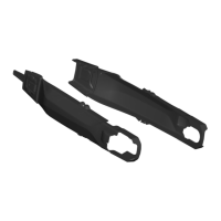
Identifies the fork protection component labeled 'A', with a quantity of 1 piece.

Part B: Fork Protection

Identifies the fork protection component labeled 'B', with a quantity of 1 piece.

Part C: Support

Identifies the support component labeled 'C', with a quantity of 1 piece.

Part D: Support

Identifies the support component labeled 'D', with a quantity of 1 piece.

Part E: Zip Ties

Identifies the zip ties component labeled 'E', with a quantity of 4 pieces.

Part F: Rubber Band

Identifies the rubber band component labeled 'F', with a quantity of 2 pieces.

Part G: Plate

Identifies the plate component labeled 'G', with a quantity of 2 pieces.

Part H: Biadhesive Velcro

Identifies the biadhesive velcro component labeled 'H', with a quantity of 1 piece.

Installation Guide

Step 1: Plate and Zip Ties Insertion

Insert plate (G) into support (C) and zip ties (E) into dedicated spaces.

Step 2: Support and Zip Ties Placement

Position support (C) and close zip ties (E) without tightening.

Step 3: Fork Protection Mounting

Mount fork protection (A) with support (C) and tighten zip ties (E).

Step 4: Plate and Zip Ties Insertion (Support D)

Insert plate (G) into support (D) and zip ties (E) into dedicated spaces.

Step 5: Support (D) and Zip Ties Placement

Position support (D), insert zip ties (E), and close them without tightening.

Step 6: Fork Protection Mounting (Support D)

Mount fork protection (B) with support (D) and tighten zip ties (E).

Step 7: Cover and Rubber Band Installation

Remove covers (A/B), insert rubber band (F) into dedicated space on both protections.

Step 8: Biadhesive Velcro Cutting

Cut the biadhesive velcro (H) in half.

Step 9: Cleaning and Velcro Application

Clean swingarm/protection, apply one side of velcro (H) to protection (A/B).

Step 10: Protective Film Removal

Once in place, remove the other protective film.

Step 11: Protection Placement and Pressure

Place protections (A/B), apply pressure to velcro areas, and remove for checking.

Step 12: Final Tightness Pressure

For better tightness, put pressure on both velcros.

Step 13: Fork Protection Mounting with Rubber Band

Mount fork protection (A) with support (C) and hook the rubber band (F).

Step 14: Fork Protection Mounting (Support D) with Rubber Band

Mount fork protection (B) with support (D) and hook the rubber band (F).

Related product manuals