ACE-6XXX User Manual
RPM sensor mounting:
Reed Speed Sensor and Magnet:
1. This sensor is universal sensor for motorcycle, find a rotang part to
install magnet (for example disk, sprocket or drivesha) and a locaon
to install the sensor where it can be aligned to the magnet.
2. Align the center of the magnet to either of the sensor marking lines or
the side of the sensor. The magnet must not travel down the body of
the sensor.
3. Installing the sensor parallel to the vibraon direcon creates oponal
an-vibraon effect.
4. Make sure the gap between the magnet and the sensor is within 8mm.
Max. 8mm
Vibration Direction
sensor
Max. 8mm
Vibration Direction
sensor
Speed Sensor Mounting:
ACEWELL has several speed sensors; the unit may include one of them.
If the model is intended to be connected to a gearbox electronic speed
output to obtain the speed reading, no speed sensor will be included.
FUNCTIONS
RPM: Digital Tachometer
1. It displays digital tachometer up to 19,990RPM and displays 19,999
rpm when tachometer is over 20,000rpm..
2. It has 2 wires to pick up RPM signal, the yellow wire is to connect to
Plug,and white wire is for signal from ECU or Ignion coil.
Shift Warning RPM
1. The funcon enables you to set up a shi warning RPM.
2. A indicator flashes when RPM reaches 500rpm before seng value.
3. Shi warning LED indicator flashes when RPM reaches seng value, and stops
flashing aer you shi gear.
Km/H or MPH: Speedometer
1. Displays speed mete r up to 399.9 Km/H or 248.5 MPH.
2. The maximum frequency of soware divider is 7K Hz.
3. With a small wheel size and large number of pulses per wheel
revoluon it may not be possible to display very high speeds.
MAX: Maximum Speed Meter
Displays highest speed achieved since last Reset operaon
AVG: Average Speed Meter
It calculates average speed from last RESET. The AVG is calculated from
TRIP1 be divided by RT.
TRIP 1&2: Trip Meter 1&2
TRIP funcon accumulates trip distance since last RESET as long as bike/
vehicle is moving.
Specific Hall sensors:
Cable drive adaptors for most bikes originally fied with cable driven
speedometers or odometers are available. When using these cables it
is necessary to divide the circumference seng by the number of
rotaons of the cable per rotaon of the wheel.
Thermo Sensor and Sensor Tube:
1. The unit includes a water temperature sensor; you may have to
purchase a suitable water pipe temperature sensor tube to install
the sensor on some bikes.
2. Cut the water pipe, insert the temperature tube into the pipe and
secure it by aached pipe clamps.
3. Screw the sensor into the tube.
4. If your vehicle is fied with a thermostat that stops water flowing to
the radiator when the engine is cold, you will not get a reading unl
the thermostat opens.
5.Custom sensors are available for carbureed bikes to replace the
original sensor.
Wire Remote Control Switch Installation:
1. Install the switch arm on handlebar.
2. Install the switch box to one of 3 fixing holes and adjust switch box to
a suitable angle.
3. Plug the switch box connector into the main unit matching connector.
Hall Effective Speed Sensor and Magnet:
1. This is universal sensor for ATV or motorcyclefront or rear wheel
installaon or motorcycle front wheel installaon. For some fitments
an accessory speed sensor holder may need to be purchased.
2. Find a rotang part to install magnet (for example disk, sprocket or
drivesha) and a locaon to install the sensor where it can be aligned
to the magnet
3. Align the center of the magnet to center of side face of the sensor.
4. Make sure the gap between the magnet and the sensor is within 5mm.
INSTALLATION & PARTS
Main Unit Installation:
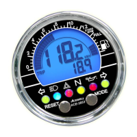
PANEL DESCRIPTIONS
FEATURES
1. Tachometer Scale
2. Needle Tachometer
3. 1st row: Speedometer
4. 2nd row: Other funcons
5. Gear Indicator
6. RESET Buon
7. MODE Buon
8. RPM Shi Warning Indicator
9. Bar Temperature gauge
10. Bar Fuel gauge
11. LED indicators
Different models have different LED indicators, each indicator symbol
means as below:
SPECIFICATIONS
ACE-64XX: 9,000rpm
ACE-65XX: 12,000rpm
ACE-66XX: 15,00rpm
Needle tachometer, integrated digital funcons and 6-10 LED
indicators for different models.
Displays needle tachometer, speedometer, bar temperature and
fuel gauges, gear indicator and one other funcon simultaneously.
Features a 99 lap mer and an oponal cable connected remote
control switch.
Gear indicator which calculates gear by comparing speed and RPM.
An oponal air temperature sensor can measure outside
temperature.
Fuel gauge full and empty resistances are fully adjustable and it can
connect to sender units with resistance range up to 990 ohms. In
reserve mode, the fuel gauge is not displayed and fuel symbol lights
when the input wire is connected to -ve. The gauge can be switched
off enrely if not required.
Flexible baery warning voltage seng from 11.0 to 15.0V.
Speedometer can show nearest 1 or 0.1 mph or km/h speed if
required by user. E.g. 100 or 100.5.
Highly visible 12mm shi warning LED indicator.
Allows end user to adjust odometer when the odometer is less than
30km / 18.6 miles.
Universal wheel circumference seng range from 1 to 3999mm.
Includes bracket, RPM sensing wire, hall or reed speed sensor,
fing kits, wiring harness and temperature sensor.
Excellent water resistant, an vibraon structure and noise
immunity design.
Power Input DC 12V
Tachometer Sensor CDI or Ignition Coil Signal
Speed Sensor Reed or hall Sensor
Temperature Sensor Thermo Sensor
Speed input divider setup 1-199 Pulses
Maximum speed input frequency 7K Hz
Wheel circumference setting 1mm-3999mm
Dimensions 130.6mm x83.4mmx31.3mm
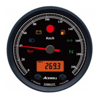
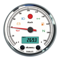
Thanks for purchasing the ATV/Motorcycle/scooter computer; this
manual is specifically designed for ACE-6XXX-XX series. Different series
have different needle tachometer scales, each series has different
models, each model has different LED indicators. You may find that the
photo has a set of LED indicators different from your computer, the
photo is for reference only.
Different series with different needle tachometer scales
are as bellows:
Main Unit
Le direcon indicator/Green
Main-beam headlamp/Blue
Right direcon indicator/Green
Hazard Warning/ Red
Parking/Green
Direcon indicator/Green
Engine oil / Red
Neutral Gear /Green
Reverse Gear /Red
Drive Gear /Green
Engine coolant temperature/ Red
P
D
R
N
Rear fog lamp/Amber
Flash Trailer/Green
Engine in out of use/ Red
Functions SpecificationsSymbol
Needle Tachometer
ACE-64XX 9,000rpm
ACE-65XX 12,000rpm
ACE-66XX 15,000rpm
Digital Tachometer
Speedometer
Maximum speed
Average speed
Temperature 1
Temperature 2
Max. Temperature
Trip meter 1&2
Trip 1&2
Odometer
12/24 Hour Clock
Riding timer
ODO
RT
RPM
Km/h / MPH
MAX SPD
AVG SPD
10-19,990 rpm,
2.4-399.9 km/h (248.5 MPH),
2.4-399.9 Km/h (248.5 MPH),
2.4-399.9 Km/h (248.5 MPH),
0
°C
-180
°C
/32
°F
-356
°F
0
°C
-180
°C
/32
°F
-356
°F
0
°C
-180
°C
/32
°F
-356
°F
<0
°C
display -L-, >180
°C
display -H-
0.0-999.9 KM /624.9Miles
0 - 999999 KM, 0-624999 Miles
AM/PM 0:00’ – 11H59’ / 23H59’
0-99H59`59``
Gear indicator
Bar-Fuel Gauge
Bar-Temperature
1-7 Bar-graphic or off mode
Maintain reminder
9999km, 9999 hours or oFF
LAP
N, R, 1, 2,…8 gears and off mode
Adjustable 10Ω -990Ω, reserve mode, or not displayed
99 laps
LAP
Total Riding Time
Total Hour meter
Voltage Gauge
TT
0-999999H
0-999999H
8.0-18.0 Volt and battery warnings
V
HRTT
Spring Washer
Washer
Rubber Pad
Fixing Screw Nut
Bracket
1.Connect either the yellow or white wire to sense the RPM signal.
2.The yellow wire can be wrapped around the spark plug lead.
a.Signal strength from the ignion coil is dependent on coil type.
b.Coil 2-5 turns around spark plug lead, the more turns the stronger the signal. A
weak signal will not show a reading on the screen whereas a very strong signal
will have a reading which is too high or very jiery. If the reading is incorrect
then try pung the 1MΩresistor which is included in the box inline in the
sensor wire.
3.If the signal is sll unstable, please try to connect the white wire to either the
ECU rev counter output or to the primary side of the coil or to the pulse wire on
an acve spark plug cap.
10R-0312652
1
11
2
4
5
7
8
10
9
3
6
1
2
MAX
ODO: Odometer
1. ODO accumulates total distance traveled.
2. ODO datemory and cannot be reset.
RT: Riding Timer
1. Calculates total running me since last RESET.
2. Counter automacally begins with movement.
TT: Total Riding Timer
1. Calculates total riding me from the beginning of the bike.
2. TT data is stored in memory, and cannot be reset.
HRTT: Hour Meter
1. Calculates total engine operaon me since installaon RESET.
2. Count automacally begins with engine starng.
3. HRTT data is stored in memory, and cannot be reset.
: 12/24 hour Clock
It displays 12 or 24 hour current me.
1 and 2:Temperature Meter 1 & 2
1. It measures and displays from 0
°C
-180
°C
/ 32
°F
-356
°F
.
2. It displays -L-
°C
or -L-
°F
when temperature is lower than 0
°C
(32
°F
) or disconnected
temperature sensor, and displays -H-
°C
or –H-
°F
when temperature is over 180
°C
or
356
°F
.
3. User can measure engine temperature with sensor 1 and ambient air temperature with
sensor 2.
4. The bar-temperature and digits of temperature as well temperature LED indicator flash
when the thermo sensor detects temperature higher than the maximum preset
temperature.
2: Low temperature warning of temperature input 2
1. Temperature input 2 has an automac low temperature warning which requires no setup
when temperature 2 input is switched on in the setup menu and a temperature sensor is
connected to it.
2. The LED indicator and the icon on the LCD flash when temperature drops below 3
℃
and stop flashing when the temperature rises above 3
℃
.
3. The digital temperature meter displays “-L-“ when temperature is less than 0
℃
MAX TEMP 1& 2: Maximum Temperature 1 & 2
Displays highest temperature achieved since last Reset operaon.
: Digital Voltage and Baery Warnings
1. It checks bike’s baery and charging systems health.
2. It has 3 modes to be set, b-on, b-oFF and b-HI, all 3 modes range is from 11.0V to 15.0V.
3. The “b-on” means baery warning on voltage, when the voltage falls below this the
LED will flash.
4. The “b-off” means baery warning off voltage, b-off voltage must larger than b-on
voltage.
5. The “b-HI” means baery high voltage, it comes on to warn that the baer has over
charging.
:
Gear Indicator
1. The gear indicator calculates gear by comparing speed and RPM then displays gear
posion.
2. User has to train the gear indicator before use it.
SCAN: Scan funcon
1.The 2nd row of LCD data will be changed automacally every preset number of
seconds if the SCAN is selected. The scan period is from 1 to 20 seconds.
2. All funcons will be manual operaons when SCAN is switched off.
: Fuel Gauge
1. Has 7 bars to indicate how much fuel remains.
2. To use as a fuel gauge, the user enters the sender ‘empty’ resistance between 10
and 990 ohms and the sender ‘full’ resistance between 10 and 990 ohms. The
computer produces a linear scale of bars between these two resistances. When less
than 10% fuel remains the gauge will flash and the warning LED if fied will light.
3. To use as a reserve indicator, connect the reserve switch to the input and put into
“rEs” mode. When the switch pulls the input to –ve the LED warning will light. On
vehicles with temperature based sensors a 68Ω 5W resistor needs to be connected
between the input wire and 12v (switched).
4. If the gauge and warning lamp are not required they can be switched off
: Bar Thermometer*
1.Have 7 bars to indicate engine temperature.
2.The 4th bar counts from boom be turned on and over temperature LED flashes when
thermometer reaches the preset warning temperature, each +/-15
˚C
lights on/off a bar
base on the 4th bar.
3.The bar-temperature flashes when the measured temperature is higher than the preset
warning temperature.
LAP:
Lap Timer
1.It can keep up to 99 sets of lap mer of each circle.
2.The funcon must be operated by an addional wiring remote control
switch or an accessory IR receiver/transmier or a magnec field sensor.
Freezing Time for Lap mer:
1.The freezing me is designed to avoid addional count signal during the set me.
2.The set range is from 1 to 20 seconds.
ATV/Motorcycle/Scooter
Computer