Thank for purchasing an Acewell ATV/Motorcycle/Scooter computer. This
manual is specially designed for the ACE-27xx/28xx series. Each model has 4-6
LED indicators. Different models have different LED indicators; a fuel meter is
optional, but all other functions are the same. You may find that the photo above
has a set of LED indicators different from your computer; the photo is for
reference only.
ATV Computer
FEATURES
SPECIFICATIONS
Power Input: 12VDC.
Speed Sensor: No Contact Magnetic Sensor.
Tachometer Input: CDI or Ignition-coil signal.
Wheel Circumference Setting: 1mm - 3999 mm (1 mm increment)
Operation Temperature: -10°C - +80°C (inner housing)
Storage Temperature: -25°C - +85°C (inner housing)
FUNCTIONS
www.acewell-meter.com
Includes analog and digital tachometer,
speedometer (300km/h), trip meter, odometer,
clock, average speedometer, maximum
speedometer, riding timer and cumulative riding
timer.
Computer unit has 4-6 built-in LEDs for different
purpose indicators.
LCD has two rows of digital and one analog
bar-graphic tachometer displays, with white LED
backlight.
Fast processor so can connect to pulse type gearbox
speed sensors.
Allows end user to adjust odometer when the
odometer is less than 30km /18.6 miles
Speedometer can show nearest 0.1 mph or km/h
speed if required by user. E.g. 100 or 100.5.
The computer's clock is always on, even when.
other functions are power-off.
Universal wheel circumference setting range of
1-3999mm.
Metric/ British system options.
Waterproof design.
INSTALLATIONS & PARTS
2.
1.
7.
3.
4.
6.
5.
8.
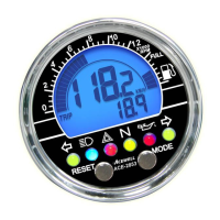
ACE-2853
PANEL DESCRIPTIONS
1. Bar Speed Scale 5. RESET Button
2. Bar Speed 6. MODE Button
3. 1st row display: Speedometer, 7. Fuel Meter Bar: (optional)
Maximum Speed 8. LED indicator symbols
4. 2nd row display: Other functions .
Left-Direction Indicator/Green
Main-Beam Headlamp/Blue
Right-Direction Indicator/Green
Hazard Warning/ Red
Parking/Green
Direction Indicator/Green
Engine Oil/Red
Neutral Gear/Green
Reverse Gear/Red
Drive Gear/Green
Engine Coolant Temperature/Red
P
D
R
N
Rear Fog Lamp/Amber
Trailer Flashers/Green
Engine "Not In Use"/ Red
BAR RPM: Bar Graphic Tachometer
1. The bar graphic tachometer reading is always displayed at the bar graph.
2. Tachometer bar graphic displays up to 12,000 RPM.
RPM: Digital Tachometer
1. RPM is displayed in 2nd row.
2. Digital tachometer displays up to 19,900 RPM.
3. Tachometer signal picked up from either CDI or Ignition coil.
Shift Warning RPM
1. Function enables you to set up an RPM shift warning.
2. Bar-graphic tachometer flashes when RPM reaches pre-set value, and stops
flashing after you shift gear.
MAX RPM: Maximum Tachometer
1. MAX RPM is displayed on 2nd row.
2. Displays highest tachometer reading achieved after last RESET operation.
SPD: Speed Meter
1. Speed meter display is on 1st row of the screen.
2. Displays speedometer reading up to 300.0 Km/H or 187.5 mph.
MAX: Maximum Speed Meter
1. MAX is displayed on 1st row.
2. Displays highest speed achieved after last RESET operation.
AVG: Average Speed Meter
1. AVG is displayed on 2nd row.
2. Calculates average speed from last RESET.
TRIP 1 & 2: Trip Meter 1& 2
1. TRIP function registers cumulative trip distance from last RESET while bike is
being ridden.
2. Display is on 2nd row of screen.
ODO: Odometer
1. ODO accumulates total distance traveled.
2. ODO data is adjustable when it is less than 30km (18.6 Miles), after that it stored
in memory and cannot be reset.
RT: Riding Timer
1. Calculates total operation time from last RESET.
2. Count automatically begins with vehicle movement.
TT: Total Riding Timer
1. Calculates total operation time from the beginning of bike use.
2. Count automatically begins with vehicle movement.
3. TT data is stored in memory, even when power is off.
RTT: Hour Meter
1.Calculatew total engine operation time from last RESET
2.Count automatically begins with engine staring.
3.RTT data is stored in memory, and couldn’t be reset.
12/24 hour Clock
It displays 12- or 24-hour current time.
Fuel Meter
1. Has 7 bargraphic indicator of fuel status.
2. Last bar flashes to indicate low fuel level.
E
13
10R-022811
RPM Sensor Mounting
CDI
Ignition Coil
RPM-INPUT
Either One
2-5 Turns
1. Signal intensity from ignition coli
is dependent on vehicle type.
2. Circles 2-5 turns around ignition coil,
with more turns creating steadily signal,
fewer turns creating weaker signal.
3. The computer can use all type of ignition
system, only if the RPM is not stable you
must sometimes add the attached 1MOhm
resistor in the wire of the RPM input.
ACE-27xx/28xx series User's Manual
ENGLISH
1 Second
1 Minute
1 Minute
9999H59'
0-9999H59’
0.00'00"- 99:59'59"
Riding Time
Total Time
Total Hour Meter
SPECIFICATIONS
2.3-300KM/h (187.5M/h)
MAX 2.3-300KM/h (187.5M/h)
AVG 2.3-300KM/h (187.5M/h)
0.0-999.9 Km (624.9 Miles)
0 - 999999 Km (0.0- 624999 Miles)
500-12,000 rpm
Bar Tachometer
Bar-Fuel Gauge
Odometer
Trip Meter
Maximum Speed Meter
Speed Meter
FUNCTIONS
500 rpm
1 Km or Miles
0.1 Km or Miles
0.1 KM/H or M/H
0.1 KM/H or M/H
0.1 KM/H or M/H
INCREMENTS
+/- 50PPM
+/- 50PPM
+/-1% or
+/- 0.1(KPH/MPH)
+/- 0.1%
+/- 0.1%
+/- 50PPM
ACCURACY
Average Speed Meter
+/-1% or
+/- 0.1(KPH/MPH)
+/-1% or
+/- 0.1(KPH/MPH)
TT
RT
RTT
ODO
TRIP 1&2
AVG
MAX
Digital Tachometer
RPM
100-19,900rpm
100 rpm
Shift Warning