AUTOMATION COMPONENTS, INC Version : 1.0
2305 Pleasant View Road Page 2 of 3 I0000141
Middleton, Wisconsin 53562 (888) 967-5224
www.workaci.com
Operating Specifications
*Note: All current sensors are shipped from the factory with the jumper set in the high range.
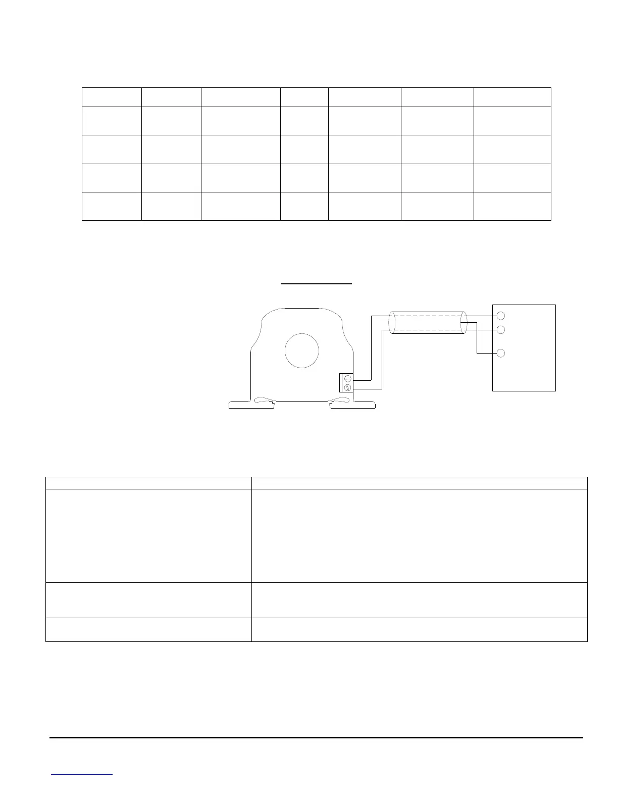
Wiring Example
_
+
Acquisition System
PLC, DDC, or Data
+ 0-5 or 0-10 VDC
(-) Signal Common
GND (Shield)
Analog Input
Connections: Shielded, twisted pair cable is
recommended for these connections.
Note: Ground shield at control
system end only!
Power: These current sensors DO NOT
need an external power source,
since the power is self-induced
from the monitored load
or conductor.
Troubleshooting
- Verify that there is current flowing thru the conductor being monitored with a
clamp-on current probe. The power for the current sensor is induced from the
conductor being monitored.
- Check the polarity of the circuit.
- Verify that the terminals are screwed down, wires are firmly in place.
- Disconnect the wires from the current sensor output. Measure the voltage
across the current sensor output with a Voltmeter to verify that the sensor is
working properly.
- Verify that the wires are terminated properly.
- In areas of high RF interference, shielded cable may be necessary to stabilize
signal.
- If you suspect that the current sensor is not reading within the accuracy
specifications, please contact the factory for assistance.
Max. Sensing
Current Voltage
Max. Current for
6 seconds
0-10 Amps
0-20 Amps
0-50 Amps
100 Amps
150 Amps
200 Amps
125 Amps
225 Amps
300 Amps
0-100 Amps
0-200 Amps
0-250 Amps
200 Amps
360 Amps
400 Amps
250 Amps
450 Amps
500 Amps
0-10 Amps
0-20 Amps
0-50 Amps
60 Amps
100 Amps
160 Amps
80 Amps
200 Amps
300 Amps
0-100 Amps
0-200 Amps
0-250 Amps
160 Amps
320 Amps
400 Amps
200 Amps
400 Amps
500 Amps
 Loading...