Do you have a question about the Acom 1011 and is the answer not in the manual?
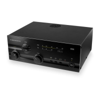
Provides an overview of the ACOM1011 HF linear amplifier and its capabilities.
Information on how to contact ACOM for technical or operating support.
Lists the items included with the ACOM1011 amplifier shipment.
Highlights key features like easy operation, no tuner needed, durability, and LED display.
Defines terms like WARNING, CAUTION, and NOTE used in the manual for user safety.
Steps for unpacking the amplifier and performing an initial inspection for damage.
Instructions for ensuring the amplifier's voltage setting matches the mains supply.
Guidance on choosing a suitable location, considering airflow and magnetic fields.
Overview of the external connections required for the amplifier.
Specifics on grounding, RF input/output, KEY-IN connection, and wall outlet preparation.
Recommends specific coaxial cable types for safe and efficient amplifier output.
Cautions regarding condensation and voltage settings before initial power-up.
Describes the main power switch, its indicator LED, and the initial power-on sequence.
Details LED bar-graphs, OPER, RTTY, A1-A2, TX LED, BAND, LOAD, TUNE controls.
Explains warning LEDs for grid overload, plate current, and general protection trips.
Step-by-step guide for powering the amplifier on and off, including warm-up.
Describes switching between OPERATE/STANDBY modes and the Auto-Operate feature.
Explains RTTY button function for reducing output power.
Details using the A1-A2 button for antenna selection.
Background on tuning, power levels, and VSWR for optimal amplifier performance.
Step-by-step instructions for tuning using LOAD, TUNE, and TRI indicators.
Guides on using the TRI indicator for tuning with LOAD/TUNE knobs.
Explains tuning nuances like gain vs linearity and adjustments for voltage variations.
Explains first degree (LED warnings) and second degree (trip to standby).
Details causes of protection trips indicated by F LED and other warnings.
Instructions and warnings for cleaning the amplifier's exterior surfaces.
Covers identification and replacement of main fuses, including ratings and types.
Advises contacting dealer for tube replacement due to complexity and danger.
Describes the amplifier's circuit components and their functions.
Lists technical specifications like frequency coverage, power output, and impedance.
Details the operational functions and features of the amplifier.
The ACOM 1011 is a self-contained HF linear amplifier designed for amateur radio use, covering all amateur bands from 1.8 MHz to 29.7 MHz. It provides over 700 W PEP (Peak Envelope Power) of output power or 500 W in continuous-duty operation, requiring less than 60 W of drive power. The amplifier is engineered to tolerate VSWR (Voltage Standing Wave Ratio) levels of up to 3:1 throughout its operating range, simplifying tuning.
Parameters:
Easy Operation and Tuning: The ACOM 1011 incorporates ACOM's exclusive True Resistance Indicator (TRI) for quick and precise tuning, typically in less than 10 seconds. This feature eliminates the need for an external antenna tuner as long as the antenna VSWR is 3:1 or lower, allowing for faster antenna changes and use over wide frequency ranges. The TRI indicator, located above the LOAD knob, guides the user to center the green LED light for optimum load resistance. Tuning is possible only in the OPER mode. The amplifier can be tuned at a quarter of nominal output power, reducing interference risk and increasing component safety.
Auto-Operate Function: The auto-operate function automatically returns the amplifier to the OPERATE mode after each protection trip, saving time and avoiding manual switching. The OPER button toggles between operate and standby modes.
Antenna Selection: The amplifier features a built-in antenna selector switch with two outputs (ANT1 and ANT2), selectable via a front panel button, providing instant choice of antennas.
Durable and Self-Monitoring Design: The amplifier is designed to safely withstand up to 240 W of reflected power, 100 milliseconds of drive spikes, and operator tuning errors. It can operate at more than half its designed output power with only 75% of nominal line voltage and tolerates deep voltage drops (down to zero for 10 milliseconds) and 15% line voltage spikes, making it suitable for portable use, field days, and DXpeditions.
LED Bar-Graph Display: The upper LED bar-graph continuously displays peak forward power (except during service functions), with an 800 W scale resolution (50 W per division). Levels below 50 W may not be detected. The lower LED bar-graph indicates reflected power up to 240 W, with a 30 W scale resolution.
Warning Indicators: LED warning indicators are provided for abnormal conditions related to grid 1 (G1), grid 2 (G2), and plate (IP) parameters. A red "F" (fault) LED illuminates during protection trips, indicating the cause.
Short Warm-up Period: Only a 30-second warm-up period is required, though 60 seconds is recommended by the tube producer. During warm-up, the amplifier remains in standby mode, and the transceiver can still be used.
Permanent Monitoring and Protection: The amplifier continuously monitors and protects plate and grid currents. The Bias Optimizer minimizes heat dissipated by the tubes, ensuring longevity.
High Voltage Protection: The high-voltage power supply design eliminates turn-on transients affecting sensitive devices on the same line circuit. The amplifier can be configured for 8 nominal line voltages between 100 and 240 V, 50 or 60 Hz.
Band Inclusion: The amplifier can be shipped with 10 and 12-meter capability disabled as required by the FCC for United States users, with options to enable these bands through the dealer.
Transceiver-Independent Operation: The amplifier operates without special signaling from the transceiver, requiring only "ground on TX" and 60 W RF drive power for full output.
Broadband Input Matching: Broadband input matching circuitry offers excellent loading characteristics for the driving transceiver from 1.8 MHz to 30 MHz.
RTTY Mode: A dedicated RTTY mode reduces output power to a maximum of 500 W for continuous-duty modes like RTTY, SSTV, or other data modes, optimizing tube dissipation without requiring tuning adjustments.
Fuses: The amplifier has two primary line (mains) fuses on the rear panel (5x20 mm, fast (quick blow) type). For 120 V AC operation, 10 A fuses are used (LITTELFUSE 0217010; Wickmann 1942100000). For 240 V AC operation, 6.3 A fuses are used (LITTELFUSE 021706.3; Wickmann 1931630000). Internal fuses on the HV PCB (2 A, slow blow) and MAINS PCB (5 A and 0.8 A, slow blow) should only be replaced by a trained service technician.
Cleaning: The outer surface can be cleaned with a soft cotton cloth lightly moistened with clean water. Solvents should not be used. The amplifier should not be opened by the user.
Tubes Replacement: The amplifier uses two 4CX250B (7203) ceramic-metal tetrodes. New tubes must be supplied as a matched pair with close electrical characteristics. Tube replacement is a complex and potentially dangerous operation involving plate idling current adjustment and should only be performed by an ACOM dealer.
Service Functions: By simultaneously pressing the OPER and RTTY buttons, the amplifier can enter a service mode to display grid 1 DC currents, grid 2 DC voltage, and combined plate current and grid 2 current on the upper bar-graph. The auto-protection system remains active in service mode.
Storage and Shipment: For shipment, the amplifier should be packed in its original carton after disconnecting all cables and the power plug. Acceptable storage environments include dry, ventilated, unheated locations free of chemically active substances, with a temperature range of -40 to +70 degrees Celsius and humidity up to 75% at +35 degrees Celsius. It can be transported by all means, including aircraft baggage compartments up to 12,000 meters (40,000 feet) above sea level. Shipping dimensions are WxDxH: 535x445x270mm, 21kg (21x17.5x10.6 inches, 46.3Lbs).
| Brand | Acom |
|---|---|
| Model | 1011 |
| Category | Linear amplifier |
| Language | English |