5.
CAREFULLY
turn the speaker over,
so
that the back side
is
facing up. Remove one
of
the
MK-121
Interface units from its carton and
set
aside the hardware needed Place the lnterface unit on the
floor at the
base
of the speaker. with the opening of
the unit facing the back
of
the speaker.
6.
You will
notice three groups of wires extending through
the rubber grommet on the speaker's firewall
plate (lower
rear
area). Vlsually identify the three wire groups as the
RED
GROUP, with a pin plug on
the end; the BLUE GROUP. with a blue sleeved hook on the end; and the WHITE GROUP, with a plain
hook on the
end.
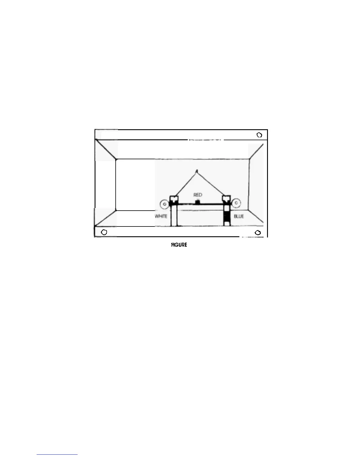
7.
(Refer to Figure
1).
Insert the pin plug into the
RED
socket on the circuit board of the interface unit.
Attach the
BLUE
hook to the board on the right side, identified
by
the blue tape
on the nylon spacer
below
the thumbscrew.
and
the
word
"
Blue
"
. Loosen the thumbscrew three turns. Place the hook
between the thumbxrewand thewasher, and tighten securely. Repeat the same procedureforthe
WHITE group,
at
the white side of the
circuit
board
0
0
(SIMPLIFIED
VIEW)
0
1
PANEL CONNECTIONS
AT
INTERFACE
8.
Push any excess wire into the rubber grommet on the back of the speaker's base.
9.
CAREFULLY, place the interface unit on the back of the speaker's base, aligning the
six
mounting
holes.
Be
careful not to pinch any wires when you set the interface
on
the metal firewall plate Using
the
six
screws
provided in your hardware packet. attach the interface unit to the
speaker's
back.
10.
Install the two casters included with
the unit into the bottom rear corners of the unit.(Thecastershave
nuts prethreaded into the stem.) When assembled and standing. the system should be
perpendic
-
ular to the floor. This perpendiculariiy can be
determlned
by
two
factors:
1)
the
type
of
floor the
speaker
is
standing on; and
2)
the amount of caster stem thread showing.
If
the system
is
to
be
positioned on a
hardwood or cement floor, the caster must be screwed in all the way(or almost
all
the way) into
the
interface unit. If the system
is
to be installed on
a
carpeted surface, the caster will
need to be
screwed in only partially. The actual setting can be adjusted when the speaker
is
standing.
NOTE
Depending on the particular room set
-
up, a slight degree
of
tilt back or tilt forward may be
desired. Thiis can be
accomplished by caster positioning. and will not cause stability problems with
the speaker system.
11.
When t
he correct caster adjustment has been obtained.
securely tighten the nut on the casterstem
against the interface unit chassis.
WARNING: The caster
WlLL
NOT support the entire weight of the assembled speaker system. When
movlng the system,
Do
NOT
tilt the speaker
off
its
base
and roll it like
o
hand truck.
To
move the
system slide the base along
the floor with the caster acting as an assist only.
2