Do you have a question about the Acoustic 134 and is the answer not in the manual?
General purpose amplifier with two 12" speakers for good bass response.
Combines special effect circuits with two 15" speakers for richer bottom end.
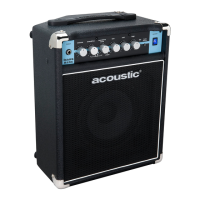
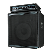
Designed for electric bass with two 15" speakers and bass-specific amplification.
For lead guitar with six 10" speakers for sustain and response.
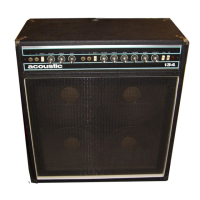
For lead guitar with four 12" speakers for maximum sound and bass.
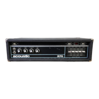
Amplifier uses modular construction for fast, on-the-spot repairs, tracking issues to plug-in boards.
Detailed technical specifications for the 150 series amplifiers, including power output, controls, and cabinet dimensions.
250W Peak, 125W RMS, 4-10" speakers, open back. Features two channels with gain, EQ, and effects.
250W Peak, 125W RMS, 2-12" speakers, open back. Features two channels with gain, EQ, and effects.
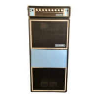
250W Peak, 125W RMS, 1-15" speaker, horn loaded. Features two channels with gain, EQ.
250W Peak, 125W RMS, 6-10" speakers in sealed system. Two channels with gain, EQ, and effects.
250W Peak, 125W RMS, 4-12" speakers in sealed system. Two channels with gain, EQ, and effects.
250W Peak, 125W RMS, 2-15" speakers in ported enclosure. Two channels with gain, EQ.
Similar to Model 146 but with 2-Altec 15" speakers.
Details the Acoustic 150 amplifier and speaker enclosure combination for rhythm/lead guitars.
Lists input types, power output, and speaker configurations for various models.
Explains the function of the 17-10 preamp board, including gain stages, tone controls, and decoupling networks.
Describes the 17-11 preamp board, covering reverb driver, FET biasing, and tone control amplifier stages.
Details the 17-12 power amp board, explaining feedback pair amplifier configuration and output transistor biasing.
Lists essential tools and instruments for troubleshooting the amplifier, such as VTVM, VOM, and oscilloscope.
Outlines initial diagnostic steps, including customer demonstration and visual inspection of components.
Provides signal levels for testing the 17-10 circuit card using an audio signal generator.
Details how to test the frequency response of the 17-10 card using an oscilloscope and specific frequency/condition settings.
Lists correct signal levels for the 17-11 circuit card when using a signal generator.
Tabulates signal levels for transistors on the 17-11 board under specified operating conditions.
Describes how to test the reverb preamp by applying signal directly to the reverb spring output plug.
Details frequency response testing for the tone amplifier Q213 using an oscilloscope.
Presents signal levels and waveforms for the tremolo oscillator and driver section.
Explains using DC voltage tables to pinpoint faulty components by comparing readings to expected values.
Lists DC voltage readings for transistors on the 17-10 preamp board under specific conditions.
Lists DC voltage readings for transistors on the 17-11 preamp board under specific conditions.
Provides signal levels for the power module without a load, tested with a signal generator.
Provides signal levels for the power module with a 4 Ohm load, tested with a signal generator.
Details how to measure power output and bandwidth, including clipping levels and frequency sweep tests.
Lists DC voltage measurements for output transistors under loaded conditions.
Lists DC voltage measurements for the power module with no load and zero signal.
Detailed circuit diagram for the 17-10 preamp board, showing components and connections.
Circuit diagram for the tremolo oscillator section of the 17-11 preamp board.
Circuit diagram for the reverb mixer and volume/tone controls of the 17-11 preamp board.
Detailed circuit diagram for the volume and tone control section of the 17-11 preamp board.
Circuit diagram for the 17-12 power module, detailing output transistors and associated components.
Illustrates the internal wiring connections within the chassis of the Model 150 amplifier.
Details pin assignments for connectors and cable routing, linking them to functions and boards.
Photographs showing the top and bottom views of the 17-10 preamp board with labeled components.
Photographs showing the top and bottom views of the 17-11 preamp board with labeled transistors.
Photographs showing the top and bottom views of the 17-12 power module with labeled transistors and components.
Photograph showing the internal wiring of the chassis, highlighting power transistors and transformers.
Lists and describes the numbered controls found on the front panel of the amplifier.
Lists and describes the numbered controls and jacks typically found on the rear panel.
Diagram illustrating the numbered positions of controls on the front panel of the amplifier.
Diagram illustrating the numbered positions of controls and jacks on the rear panel of the amplifier.
Addresses amplifier blowing fuses due to short circuits or overheating and distortion at low volume.
Covers intermittent distortion, reverb issues, and feedback/oscillation from the reverb system.
Addresses buzzing sounds, hum, loss of power or bass, and no output on speaker jack #2.
Lists mechanical parts like covers, chassis, and electrical components such as capacitors and circuit boards, with Acoustic Part Numbers.
Lists various resistors, capacitors, and hardware components with their specifications.
Lists remaining components like transistors, switches, fuse holders, and transformers.
Details amplifier specifications including gain, noise ratio, power output, inputs, fuse, and control types.
Lists specifications for 154 and 152 speaker cabinets, including speaker complement, design, construction, size, and shipping weight.
Lists specifications for 155, 134, and 135 speaker cabinets, including speaker complement, design, construction, size, and shipping weight.
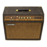
| Type | Bass Amplifier |
|---|---|
| Inputs | 1 x 1/4" Instrument Input |
| Controls | Bass, Treble |
| Speaker Size | 1 x 15" |
| EQ | Bass, Treble |
| Weight | Approximately 60 lbs |