6 7
Wired Connectivity:
DAB / FM – F-connector socket, allows a connection to a DAB / FM antenna (indoor antenna supplied).
Analogue audio input – 3.5mm stereo jack (on same connector as optical digital) allows a connection to an
external analogue audio source such as a CD player.
Optical digital input – mini TOSLINK (on same connector as analogue) allows connection to an external
digital audio source such as a TV.
Speaker output – Imo sockets, allowing connection to a pair of passive speakers.
Analogue line output – 3.5mm stereo jack, allows a connection to an external sub-woofer, amplier or the
input of a another E120.
Wireless Connectivity:
Bluetooth® – An international wireless connection used for streaming audio from all compatible devices.
Control:
AVRCP – A Bluetooth control protocol that synchronises your device control of Volume and Mute for easy
integration of our Q Acoustics speaker.
Infra-red – A waterproof remote control for easy line of sight basic congtrol .
Acoustic:
Stereo / mono switch – Sets the speaker output as either separate left and right, or combined mono outputs.
Fixed / variable line out switch – Sets the line output as either variable (adjusts with speaker volume) or xed.
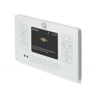
Feature summary
1 x User guide +
installation guide
E120
INSTALLATION GUIDE
E120
USER GUIDE
1 x Antenna extension
cable + adaptor
1 x Indoor DAB
antenna
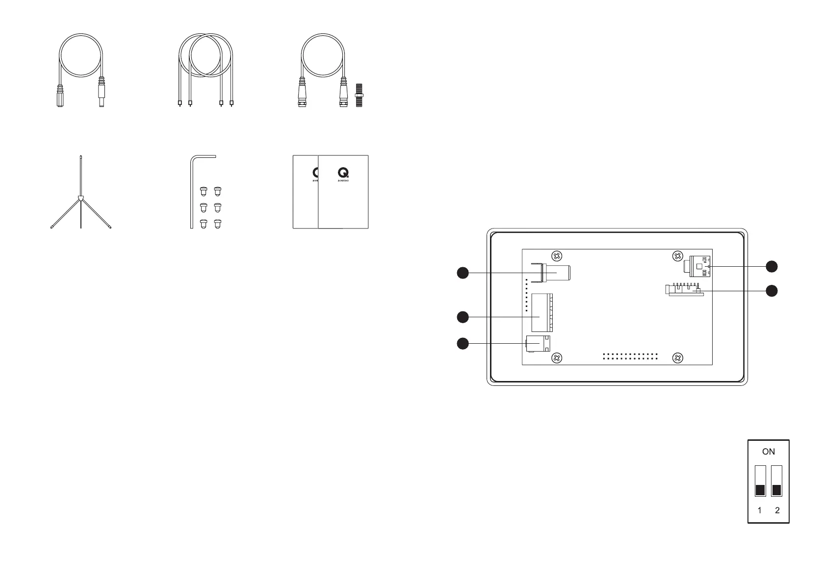
E120 is supplied with all the cables and wall box to fully install the system. Please refer to the ‘E120
installation manual’ which provides all details on the positioning and cable requirements of the system.
Physical connectivity:
1. DAB / FM ANTENNA – Connect a suitable DAB / FM antenna using the supplied connecting cable.
2. SPEAKER OUTPUTS – Connect the left and right speakers here using the supplied connectors.
3. DC POWER – Only use the supplied power supply and adapting extension cable to power the unit.
4. LINE OUTPUT – A separate amplier or sub-woofer can connect using a 3.5mm stereo jack socket.
5. AUX INPUT – Connect an external input here such as TV, use analogue 3.5mm stereo jack or mini
TOSLINK optical digital.
Connecting the system and powering on
3
2
1
4
5
Configurable Switches:
There are two small switches mounted on the lower PCB that adjust the audio mode
outputs. After making a switch position change you will need to power down the
E120.
SWITCH 1 OFF – Line output is variable, adjusts with amplier volume.
SWITCH 1 ON – Line output is xed at 100%
SWIITCH 2 OFF – Amplier speaker outputs are in stereo mode with separate left
and right channels.
SWITCH 2 ON – Amplier speaker outputs are in mono mode with both left and right
channels combined on both speaker outputs.
2 x 7m speaker cable
6 x Rubber grommets
+ 1 x extraction tool
1 x Power supply
extension cable