Compact FLASH Digital Audio System
11
Optional Contact Outputs
Starting with CFSound v1.5 firmware, an optional contact output may also be associated with a sound.
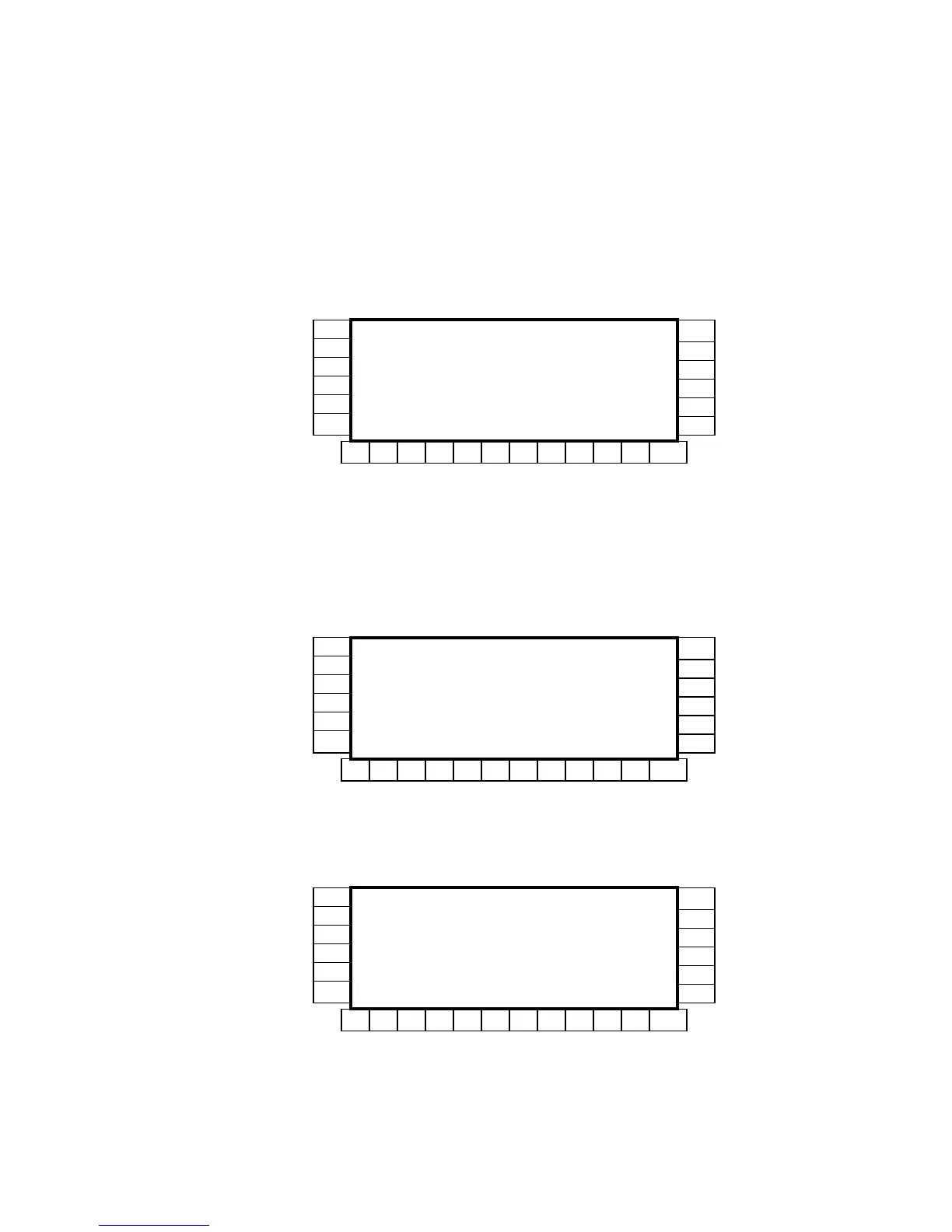
There are two configurations of Maxi SPST Relay 24 modules that may be used depending upon the pack-
aging and/or application requirements..
When the CF Sound unit is not packaged in the Lansing enclosure (OEM model) a Maxi SPST Relay 24
module may be installed by stacking on connector EXP. This module should be set to Base + 0 address via
jumper JB1. The numbering of the contact outputs around the periphery of the module occurs in three
groups of eight outputs as follows:
This precludes the use of the eight contact inputs on the front of the base CF Sound module from activating
contact outputs since these inputs are numbered 01 - 08.
When the CF Sound unit is packaged in an enclosure, only a single Maxi module without connectors on the
short sides may be installed. To utilize contact outputs with this configuration, or when contact outputs are
required for contact inputs 1 – 8, a special, partially populated Maxi SPST Relay 24 module is required.
This special module eliminates the connectors, relays and chips on the short sides of the PCB, and has a
composite connector centered across the middle 16 pins of J2 and J3. This module should be set to Base + 4
address via jumper JB1. In this configuration, the numbering of the contact outputs is as follows:
An OEM Compact Flash Sound module (CF Sound) may also utilize expanded contact inputs to trigger
sounds by stacking a Maxi Contact Sense 24 module on connector EXP. This Contact Sense 24 module is
configured for Base + 0 address via jumper block JB1. In this configuration, the numbering of the contact
inputs is as follows:
16
15
14
13
12
11
10 09 24 23 22 21 20 19 18 17 32 31
30
29
28
27
26
25
Maxi SPST Relay 24
Base + 0
08 07 06 05 04 03 02 01
Partial Maxi SPST Relay 24
Base + 4
16
15
14
13
12
11
10 09 24 23 22 21 20 19 18 17 32 31
30
29
28
27
26
25
Maxi Contact Sense 24
Base + 0