Do you have a question about the Acson international A5MAC 210D and is the answer not in the manual?
Explains the model naming convention and its components.
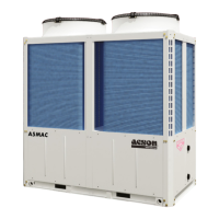
Provides a general introduction to the ACSON A5MAC-D series chiller/heat pump.
Details the environmentally friendly R410A refrigerant used in the units.
Highlights the design features contributing to reduced operational noise.
Describes the factory-sealed system simplifying installation for users.
Explains the unit's ability to modulate capacity electronically for efficiency.
Details how units can be combined to meet varying capacity requirements.
Notes the reduced dimensions and weight for easier placement.
Emphasizes modulating capabilities, controlled starting, and QA tests for reliability.
Mentions optional fan for specific exhaust duct requirements.
Lists features, modes, settings, and functions of the control system.
Provides key technical specifications and data for R410A models.
Details specifications for the evaporator section, including material and water flow.
Provides data on the condenser, including material, tube type, and fin specifications.
Lists details about the condenser fan, such as blade material and air volume.
Specifies compressor type, quantity, and refrigerant used.
Indicates the refrigerant type and charge amount.
Outlines the safety devices incorporated into the unit, like pressure switches.
Shows physical dimensions and mounting hole details for specific models.
Illustrates acceptable ambient and leaving water temperature ranges for operation.
Provides the wiring diagram for A5MAC210/230D models.
Specifies the required environmental and operational conditions for installation.
Details clearance requirements and environmental limits for unit placement.
Provides guidelines on required space for unit installation and module assembly.
Outlines the essential water quality parameters for system operation and longevity.
Covers crucial aspects of designing pipe systems for air conditioning.
Lists the maximum, rated, and minimum water flow rates for different models.
Lists essential checks before powering on the unit.
Details checks to perform after the unit has stabilized operation.
States that only trained technicians should perform repairs.
Outlines regular maintenance tasks for optimal performance.
Details periodic checks for the compressor, including sound and current.
Lists periodic checks for the controller, such as parameter settings and protectors.
Specifies checks for the plate heat exchanger, including water quality.
Mentions cleaning the fin heat exchanger periodically.
Covers checks for filters and bolt tightness.
Recommends closed systems and lists anti-corrosion measures.
Discourages open systems due to susceptibility to issues.
Describes once-through systems and their potential issues.
Shows the diagram for connecting power cables to the unit.
Illustrates connections for pumps and other components on the PCB.
Details the connection requirements for communication wiring between units.
Provides the physical dimensions of the wired controller.
Illustrates how to install the wired controller.
Lists the key features and capabilities of the AC305 controller.
Explains how to operate and use the wired controller's functions.
Describes how to view unit operating status and parameters via the controller.
Details how to set various parameters when the unit is in standby mode.
Explains how to set the current time and day of the week.
Guides on setting timed ON/OFF operations for the unit.
Explains how to initiate a manual defrost cycle.
Describes how to reset the controller.
Details how to lock the controller keypad to prevent accidental changes.
Lists error codes and their corresponding symptoms for controller stoppages.
Explains error codes indicated by LED lights and their meanings.
Lists causes and solutions for communication failure between controller and master unit.
Addresses causes and solutions for water pump motor overload issues.
Details potential causes and corrective actions for insufficient water flow alarms.
Explains causes and solutions for high-pressure issues in System 1.
Outlines causes and solutions for low-pressure issues in System 1.
Details causes and solutions for high-pressure issues in System 2.
Covers causes and solutions for anti-freezing protection failures.
Addresses causes and solutions for electric heater overload.
Discusses issues related to ambient temperature extremes.
Explains causes and solutions for low suction superheat in System 1.
Lists causes and solutions for communication failures between master and slave units.
Addresses causes and solutions for high suction temperature in System 1.
Details causes and solutions for high discharge temperature in System 1.
Covers causes and solutions for high suction temperature in System 2.
Details causes and solutions for high discharge temperature in System 2.
Addresses causes and solutions for low pressure in System 1.
Explains causes and solutions for low suction superheat in System 1.
Discusses causes and solutions for refrigerant leaks in System 1.
Covers causes and solutions for refrigerant leaks in System 2.
Details causes and solutions when System 1 discharge temp sensor fails.
Addresses causes and solutions for System 2 discharge temp sensor failure.
Covers causes and solutions for System 1 middle heat exchanger sensor failure.
Details causes and solutions for System 2 middle heat exchanger sensor failure.
Addresses causes and solutions for main pipe leaving water temp sensor malfunction.
Covers causes and solutions for entering water temperature sensor failure.
Details causes and solutions for leaving water temperature sensor failure.
Addresses causes and solutions for ambient temperature sensor failure.
Covers causes and solutions for System 1 heat exchanger outlet temperature sensor failure.
Details causes and solutions for System 2 heat exchanger outlet temperature sensor failure.
Addresses causes and solutions for System 1 suction temperature sensor failure.
Covers causes and solutions for suction temperature sensor failure in System 2.
Details causes and solutions for System 2 low pressure sensor failure.
Addresses causes and solutions for System 1 low pressure sensor failure.
Explains causes and solutions for memory failure.
Discusses causes and solutions for the system failing to start up.
Covers causes and solutions for System 1 fan motor overload.
Details causes and solutions for System 2 fan motor overload.
Addresses causes and solutions for a large temp difference in the water system.
Covers causes and solutions if water temperature sensors are swapped.
Details causes and solutions for master unit entering water temperature sensor failure.
Addresses causes and solutions for compressor overload in System 1, unit 2.
Covers causes and solutions for compressor overload in System 2, unit 2.
Discusses causes and solutions for abnormal discharge temperature in System 1.
Details causes and solutions for abnormal discharge temperature in System 2.
Explains causes and solutions for DIP setting errors.
| Brand | Acson international |
|---|---|
| Model | A5MAC 210D |
| Category | Chiller |
| Language | English |