1-3
English
Dimension A
Minimum
Distance, mm 300 1000
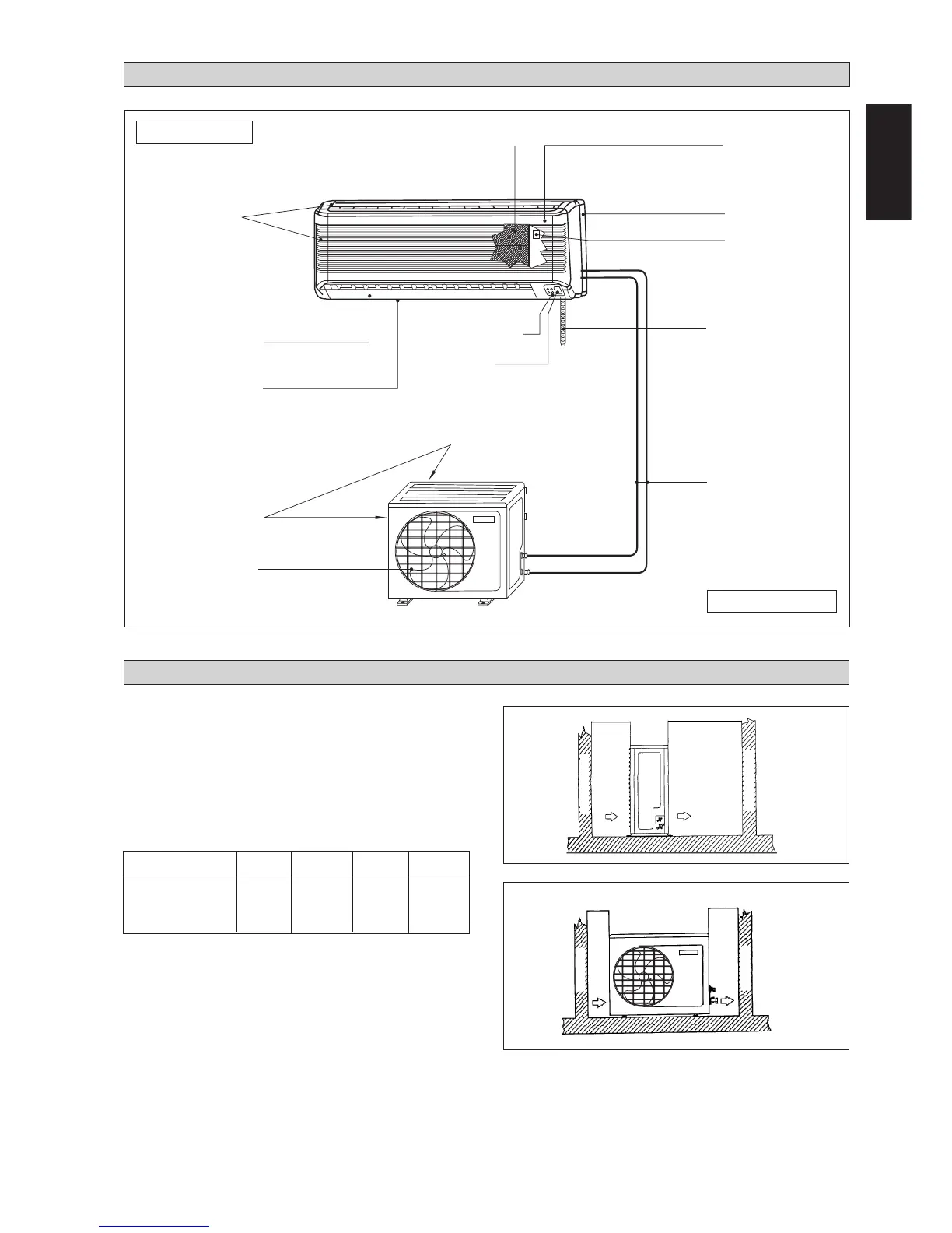
INSTALLATION DIAGRAM
Air Intake Grille
Air Discharge
Grille
Air Intake
Refrigerant Piping
Drain Hose
Front Frame
Back Housing
On/Off Switch
Air Filters
Indicator Lights
Signal Receiver
Air Discharge
Louver
Outdoor Unit
Indoor Unit
INSTALLATION OF THE OUTDOOR UNIT
Obstacle
Return Air
Discharge Air
Service Access
The outdoor unit must be installed in such a way, so as to
prevent short circuit of the hot discharged air or obstruction
to the smooth air flow. Please follow the installation clear-
ance shown in the figure. Select the coolest possible place
where intake air temperature is not greater than the outside
air temperature (maximum 45°C/113°F).
Installation clearance
Note: If there is any obstacle higher than 2m, or if there is
any obstruction at the upper part of the unit, please allow
more space than the figure indicated in the above table.
Air Discharge
Nozzle
Obstacle
Obstacle
Obstacle
Return Air
A
B
C
D
Air Intake
(in) (11.8) (39.4) (11.8) (19.7)
B C D
300
500
 Loading...