• A dedicated channel plan is required for Sweep
Loopback, and building the plan is similar to building a
reverse plan (Figure 12). The channel plan is constructed
by selecting a start / stop frequency and interval between
frequencies. Channel plans may be built from 5-1000
MHz. Channel frequencies may be edited as needed. Tilt
channels are enabled at the highest and lowest frequen-
cies built in the plan.
*WARNING! TO AVOID INTERFERENCE WITH ACTIVE
SERVICES ON THE CABLE SYSTEM, MAKE SURE THAT
THE LOOPBACK SWEEP TEST IS PERFORMED OUT-OF-
SERVICE, OR BUILD SWEEP CHANNELS AROUND ANY
ACTIVE SERVICES!
• After the channel plan is built, select the desired sweep
insertion level into the device being tested (Figure 13).
• Press the front panel sweep key to begin the Sweep
Loopback measurement. A reference will typically need
to be established to account for any test cable losses or
mismatches. This is accomplished by connecting the test
cables from the SDA-5000 transmitter output (OPT port)
to the input port. Press the FUNCTION key followed by
the #6 key to store a reference (Figure 14).
Note: The level reading is an absolute measurement
(example: dBmV units) prior to establishing a refer-
ence. After the reference has been established, the
meter will read in relative units (dB).
• Connect the transmitter output of the SDA-5000 to the
input of the DUT, and connect the receiver input to the
output of the DUT. In Figure 15, the sweep loopback
measurement is used to check the frequency response of
a line extender.
Figure 11
Figure 12
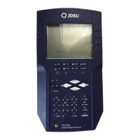
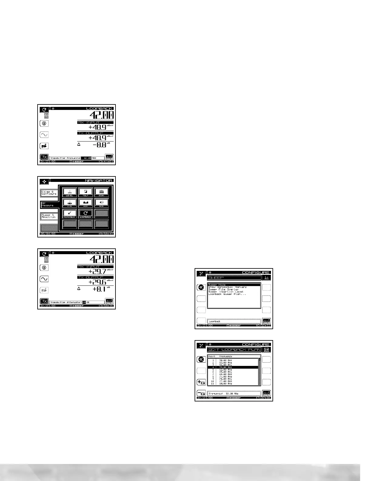
• The transmitter is at the maximum output of +50 dBmV
when initially enabled. The user may adjust the transmit-
ted output level by scaling the attenuator (Figure 10) for
the desired output level.
• Test point compensation can be enabled, if desired, for
the CW Loopback mode. This mode recognizes the for-
ward test point compensation values, regardless of the
frequency that is being generated. If enabled, the test
point compensation value will be displayed in the lower
left corner of the Loopback display.
Figure 8
Figure 9
Figure 10
Loopback Sweep
Transmitting and receiving a sweep signal from a single SDA-
5000 (OPT. 2 required) meter can be achieved through the
Loopback Sweep mode. The Loopback Sweep mode is an
ideal solution for characterizing frequency response of net-
work active and passive devices.
• The Loopback Sweep feature is selected in the SWEEP
MODE menu in the SWEEP CONFIGURATION menu
(Figure 11). Cabling the Sweep Loopback is nearly identical
to the CW Loopback. The SDA-5000 transmitter output
(OPT. port) is cabled to the input of the device under test
(DUT). The SDA receiver input is cabled to the DUT output.
 Loading...