EasyManua.ls Logo

ACTi A21 - Page 18

ACTi A21
31 pages
Print Icon
To Next Page IconTo Next Page
To Previous Page IconTo Previous Page
Loading...
www.acti.com
Hardware Manual
18
DI/DO Connection Specifications
The table below shows the DI/DO connection specifications:
Device
DI
Connection design
TTL - compatible logic levels
Voltage
To trigger (low)
Logic level 0: 0V ~ 0.6V
Normal (high)
Logic level 1: 2.8V ~ 5V
Current
10mA ~ 100mA
DO
Connection design
Transistor (Open Collector)
Voltage & Current
< 24V DC, < 100mA
Typical Connection
Based on these specifications, if the DI device has a voltage of 0V ~ 5V or the DO device has a
voltage of < 24V (< 100mA), then the camera can supply internal power to these devices and
there is no need to connect the DI/DO device to an external power source.
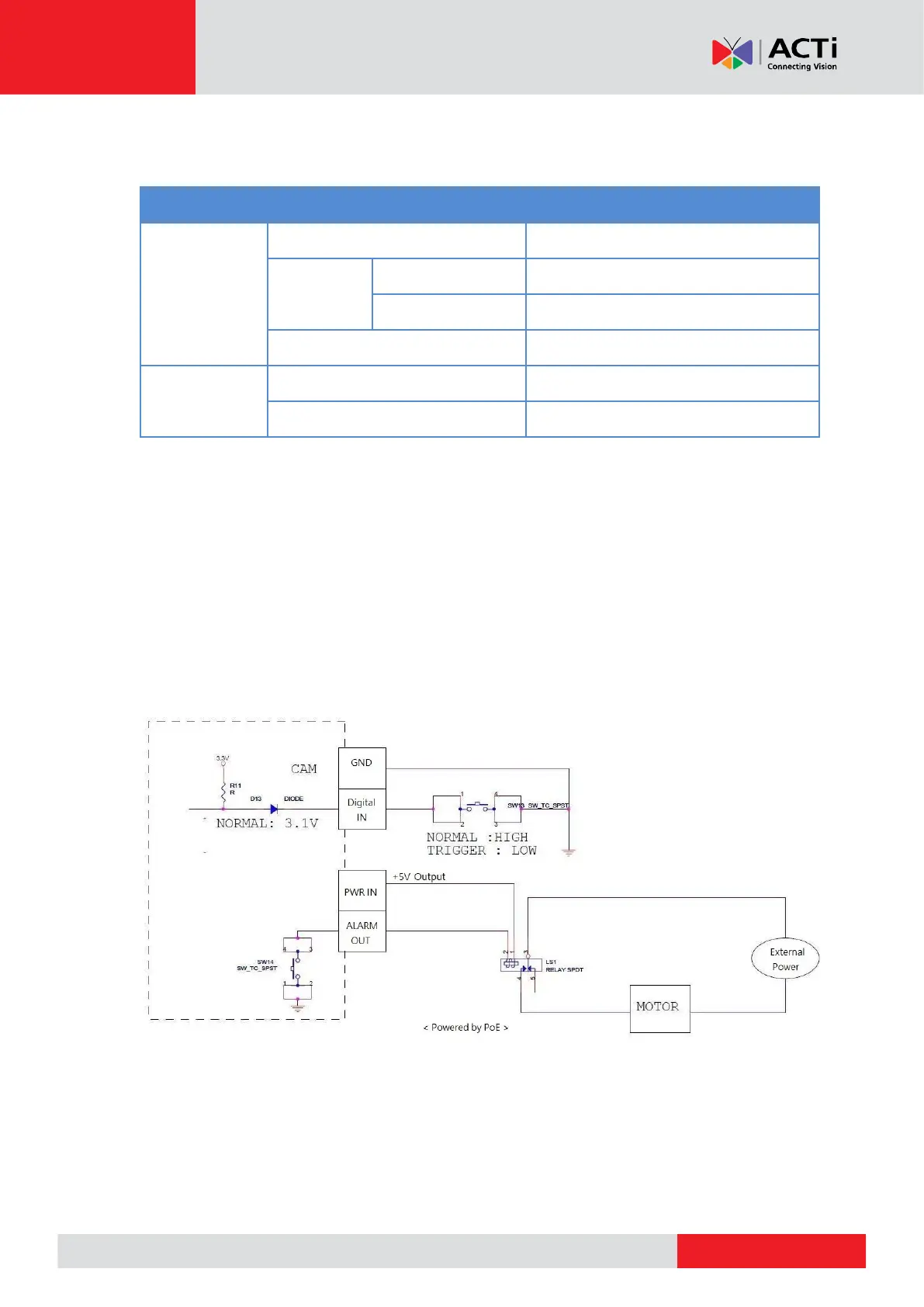
Use the GND and DI pins to connect a DI device and use the 12V and DO pins to connect a DO
device. See wiring scheme below:
NOTE: If the camera is powered up by PoE, the DC12V connector can only provide DC 5V of
power to a digital output device.

Related product manuals