Hardware Manual
9
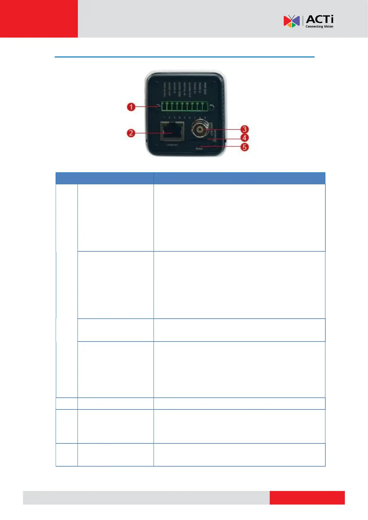
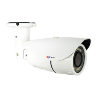
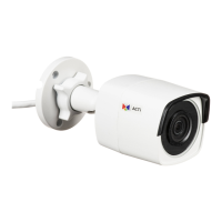
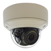
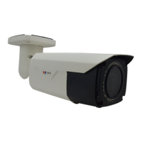
Physical Description
In case the camera is connected to a non-PoE
(Power over Ethernet) switch, use this connector
to connect the camera to an external power
adapter (not included) to power up the camera.
This connector can also be used to power up a
digital output device.
Digital Input / Output
(DI/DO)
This connector connects to digital input or output
devices, such as an alarm trigger, panic button,
etc. Digital Input (DI) and Digital Output (DO)
devices are used in applications like motion
detection, event triggering, alarm notifications,
etc.
This connector connects to audio input and output
devices, such as microphones and speakers.
Connects to a serial port device, such as a PT
scanner (sold separately), using the RS-485
protocol. Use the supplied terminal block to
connect the wires from the serial device to the
camera.
Connects to a network using an Ethernet cable.
Connects to an analog video output device with
BNC connector.
NOTE: Not available on A28, A29, A213 models.
Insert a memory card into this slot for local
recording purposes. . See How to Install /