Hardware Manual
27
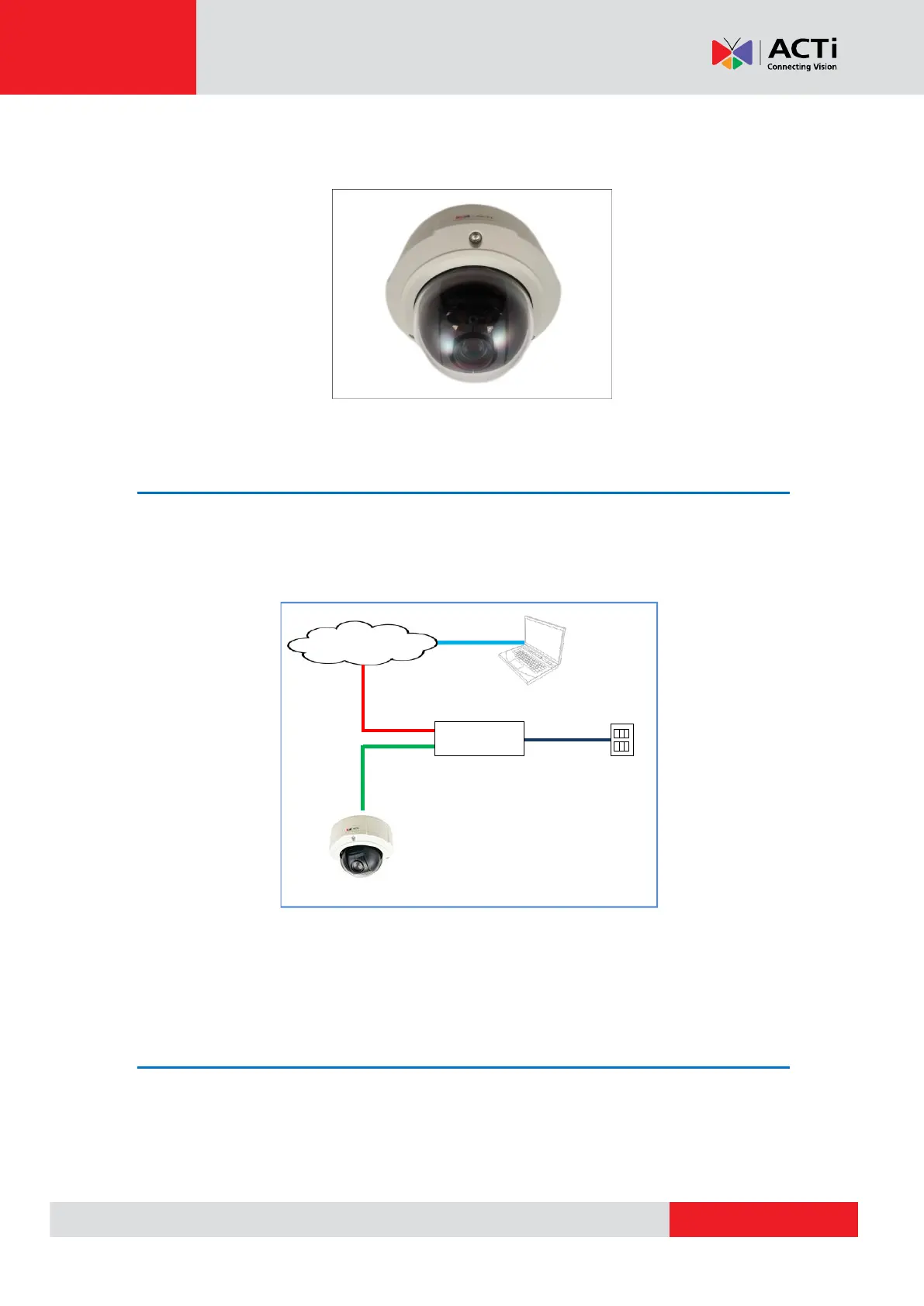
2. Remove the plastic covering the dome cover. Final installation will look like the illustration
below.
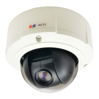
Step 6: Connect to the Network
Connect the other end of the network cable to a switch or injector. Then, connect the switch or
injector to a network or PC and a power source. See Power-over-Ethernet (PoE) example
connection diagram below.
PoE Injector /
PoE Switch
Ethernet Cable
(Data + Power)
In case of using a non-PoE switch, power up the camera using a power adapter (not
supplied). As needed, power up the other connected devices.
Step 7: Access the Camera Live View
See Accessing the Camera on page 42 for more information on how to access the Live View of
the camera.