EN
FR
NL
ES
IT
DE
PL
RU
en
21
WaterMaster 25 - 35 - 45 - 70 - 85 - 120 : A1006482 - 664Y7300 • D
TECHNICAL CHARACTERISTICS
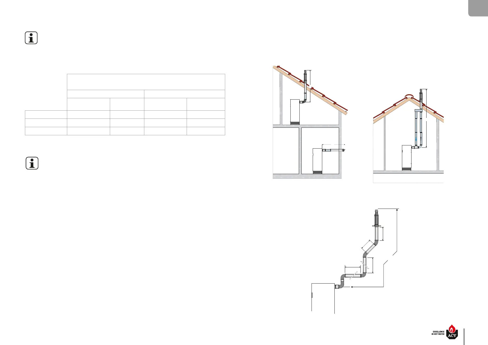
Example of verification of the flue pipe length (L) in a concentric flue pipe system for
WaterMaster 35 (80/125):
The method is explained through an example.
Figure 1 : The assembly is comprised of:
1 pipe with a measurement unit + 3 x 90° elbows + 6 meters of straight pipes + 2 x 45° elbows
• Method :
a) Using the above table, calculate the length in meters of the whole flue pipe assembly:
1 + (3 x 2) + (6 x 1) + (2 x 1) = 15 m
b) Compare the resulting value with the maximum length (39 m). This flue pipe length is within the
recommended range.
Flue pipe length (L)
(corresponding length in meters of straight pipe)
WM 25 - 35 - 45 WM 25 - 35 - 45 - 70 - 85 - 120
Concentric ue pipe
Ø 80/125 mm
Parallel ue pipe
Ø 80 mm
Concentric ue pipe
Ø 100/150 mm
Parallel ue pipe
Ø 100 mm
1 m straight pipe 1 m 1 m 1 m 1 m
90° elbow 2 m 2.3 m 2.2 m 3.7 m
45° elbow 1 m 1 m 1.3 m 2.3 m
CALCULATION OF THE FLUE PIPE LENGTH
When connecting the flue pipes, make sure not to exceed the maximum flue pipe length, recommended for the product, otherwise the system pressure might decrease.
The ue pipe pipe length can be calculated using the method shown below. Please refer to the tables below indicating the values in meters, applied to each of the connection components. Then compare the calculation result
to the recommended maximum ue pipe length indicated in the table on previous page.
The equivalent length for pipes equipped with a measuring unit is equal to a 1 meter
straight pipe
1000 mm
1000 mm
2000 mm
2000 mm
L
Fig. 1
Concentric connection Parallel connection
 Loading...