WaterMaster 25 - 35 - 45 - 70 - 85 - 120 : A1006482 - 664Y7300 • D
en
30
EN
FR
NL
ES
IT
DE
PL
RU
TECHNICAL CHARACTERISTICS
ELECTRICAL CHARACTERISTICS WATERMASTER
®
120
WaterMaster
Main Characteristics
120
Rated voltage V~ 230
Rated frequency Hz 50
Electrical consumption
Max. W 327
Min. W 70
Electrical consumption at
30% load
W 74
Electrical consumption in
standby
W 4
Rated current (Fuse) A 16
Class IP 20
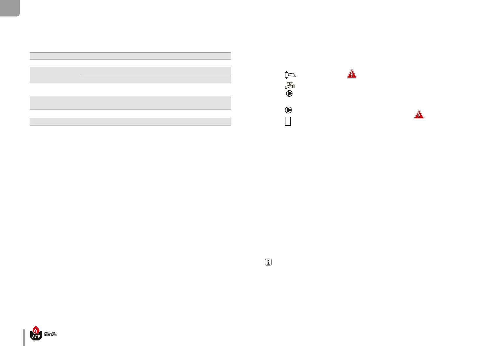
Key
1. 230 V power supply plug
2. Ground
3. ON/OFF master switch
4. Gas valve
5. Burner power supply
6. Terminal block for optional items
: Alarm (ERR terminal)
: DHW charging pump (DHW terminal)
7. Terminal block for optional items:
: Pump (P3 and P4 terminals)
: Flame terminal (versatile connection according to conguration)
8. Burner PWM plug
9. NTC5 ue gas temperature sensor
10. NTC2 primary circuit return sensor
11. NTC1 primary circuit supply sensor
12. Gas pressure switch
13. NTC - Low temperature circuit
14. High limit switch
15. Low water pressure sensor
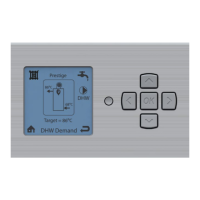
16. PCB (Display)
17. ACVMax programmation plug
18. A & B Modbus (option)
19. NTC3 DHW sensor
20. NTC4 outdoor temperature sensor (option)
21. Room thermostat 1 (option)
22. 0-10 Volt (option)
23. Room thermostat 2 (option)
24. Ignition and ionization cable
25. Connection for Interface Control Unit (option)
26. 5AT slow-blow fuse (3x) for internal and optional circuits*
27. Modulating pump PWM
* 5AT slow-blow fuse (2x) for internal circuits and connection of DHW and Flame output + 5AT slow-blow fuse (1x) for connection of
Alarm, P3 and P4 (connector P14).
2 spare 5AT slow-blow fuses are located on the back side of the electrical box, for fuse replacement, if required.
230 VAC OUTPUT !
230 VAC OUTPUT !