Do you have a question about the Adcom GFA-5802 and is the answer not in the manual?
Procedure to adjust amplifier idle current by setting bias pot R61 for stable voltage across resistor R88.
Procedure to adjust DC offset at speaker terminals using pot R179 on the input board for 0mV.
Components for the ADCOM GFA-5802 Display PCB, including resistors, LEDs, and switches.
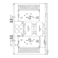
Components for the ADCOM GFA-5802 Power Supply PCB, such as diodes, rectifiers, capacitors, and transformers.
Components for the ADCOM GFA-5802 Input PCB, listing transistors, diodes, and capacitors.
Components for the ADCOM GFA-5802 Amplifier PCB, including FETs, transistors, ICs, diodes, capacitors, and resistors.
List of chassis-related hardware, connectors, power cord, and owner's manual for the ADCOM GFA-5802.
Procedure to add a 3.6V zener diode to resolve objectionable pops or squeals when the amplifier is powered off from an external source.
Guidance on ordering and replacing matched MOSFETs for the GFA-5802 amplifier to ensure proper performance.
Corrections to the GFA-5802 Service Manual's bias alignment procedure and component part numbers for transistors.