Do you have a question about the Adcom GFA-585 and is the answer not in the manual?
Warnings about electric shock, opening the unit, lightning symbols, and polarized plugs.
Instructions on unit placement, ventilation, heat source avoidance, and power cord routing.
Avoid water/moisture, clean as instructed, unplug when unused, prevent object/liquid entry.
Servicing by qualified personnel only, outdoor antenna grounding requirements.
Manual helps understand correct operation, features, and functions for maximum performance.
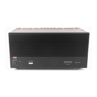
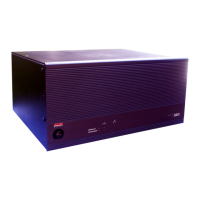
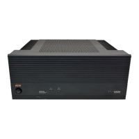
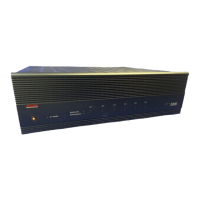
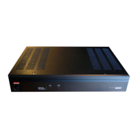
GFA-585 is stereophonic version of GFA-565, known for superb performance into difficult loads.
Caution with connections due to high peaks; disconnect power, discharge capacitors (up to 5 min).
Amplifier drives low impedance/reactive loads well, maintaining low distortion, unlike some designs.
Triple-Darlington output, no protection circuitry, massive power supply, and anti-sticking circuit.
Minimizes sonic deterioration, allows DC amplification, and reduces DC offset.
Double-differential cascode stages regulated for optimal low-level operation.
Uses OFC wiring, high-grade parts, and fine film capacitors in critical circuits.
Read Limited Warranty card for details, limitations, and benefits.
Verify serial numbers match; notify ADCOM if altered or missing.
Inspect for damage; save packing materials for claims; notify dealer immediately of damage.
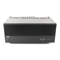
Ensure adequate air circulation for heatsinks; keep away from heat sources and obstructions.
Avoid stacking components; use vented cabinets; ensure top/bottom/side slots are clear.
For demanding loads; consists of a top plate with a variable cooling fan; easily installed.
Use optional adaptors; insulate chassis from metal rack rails to prevent ground loops.
Ensure power is OFF, cord disconnected, and components off before making connections.
Use high-quality, low-capacitance RCA cables for unbalanced inputs; 50k ohm impedance.
High-grade 5-way binding posts for loudspeakers; connect LEFT/RIGHT correctly.
Connect polarity correctly; use appropriate AWG wire gauge based on length.
Low capacitance cables are crucial; test loudspeaker phasing for correct stereo image.
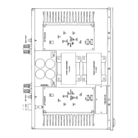
Illustration of rear panel connections including inputs, outputs, and fuses.
Use banana plugs, spade lugs, or tinned wire; handles loads down to 2 ohms.
Paralleling speakers lowers impedance; may trigger thermal protection or blow fuses.
Test phase using mono audio; reverse leads if image is imprecise or shifts.
Protect output stages; blown fuse indicated by POWER LED glowing, no audio.
Wait 5 minutes after power off before connecting/disconnecting speakers to prevent fuse blows.
Amplifier protects reliably; other circuits may degrade audio; avoid abuse.
Do not connect while ON or use 'thumb test' to prevent damage.
Use only specified fuse types; substitutes can cause damage, fire, or void warranty.
Use Phillips screwdriver, turn cap counterclockwise to remove; reverse for replacement.
Heavy-duty cord; use dedicated 15A/20A branch circuit for best performance.
Protects circuits; POWER LED not glowing may indicate blown fuse.
Unplug cord before replacing; use correct types; check for repeat blowing.
Approved fuse types listed for 120VAC/60Hz operation.
Controls power to transformer and circuits; push top to ON, bottom to OFF.
Indicates power ON; does not confirm all circuits operational; affected by AC fuse/DC fuses.
Internal thermostat protects transformer; resets automatically when cool.
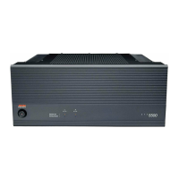
Diagram showing power, LEDs, and channel indicators on the front panel.
Detects various distortions; LEDs light at 1% distortion, flicker normally at high volume.
Bright LEDs indicate overdriving; lower volume to prevent damage or fuse blows.
Shuts down amplifier if heatsink reaches 85°C; LED indicates activation.
Caused by high power/low impedance; prevent by reducing volume or installing FAN OPTION.
No power and no thermal LED may indicate a blown AC LINE FUSE.
Clean panel with damp cloth; do not spray liquids or expose to moisture.
Contact ADCOM Technical Service for questions or difficulties.
Requires Return Authorization; ship prepaid via UPS/approved carrier; no Parcel Post.
250W/8 ohm, 400W/4 ohm ratings; THD+N, IM distortion values provided.
Frequency response and power bandwidth specifications.
Dynamic headroom, signal-to-noise ratio, and gain specifications.
Input impedance, sensitivity, damping factor, and rise time specs.
Semiconductor complement, power consumption, and dimensions/weight.