This document provides assembly instructions for the Adeept Flash Christmas Tree DIY Kit, a colorful 3D LED Christmas tree kit. The kit allows users to build a decorative electronic Christmas tree with blinking LEDs, offering an engaging and educational experience in electronics assembly.
Function Description
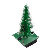
The Adeept Flash Christmas Tree DIY Kit, once assembled, functions as a decorative electronic Christmas tree featuring colorful, blinking LEDs. The circuit is designed to automatically flash the LEDs, creating a dynamic and festive light display. It operates on a 4.5V power supply, typically provided by three AA batteries, or can be powered via a 5V DC input using a USB to DC 3.5mm cable. The core functionality relies on a multi-vibrator circuit, which uses transistors and capacitors to create the oscillating signals that drive the LEDs. The kit includes three main PCB boards (CTR-30A, CTR-30B, and CTR-30C) that are assembled in layers to form the 3D tree structure. The CTR-30A and CTR-30B boards hold the majority of the LEDs, resistors, capacitors, and transistors, forming the blinking light circuits. The CTR-30C board serves as the base, housing the power input, battery box connection, and a self-locking switch to control the device's power.
Usage Features
The Adeept Flash Christmas Tree DIY Kit is designed for hands-on assembly, making it suitable for hobbyists, students, or anyone interested in learning basic electronics. The assembly process involves soldering various electronic components onto printed circuit boards (PCBs).
Assembly Process:
- Component Identification: The manual provides a comprehensive list of components, including resistors, electrolytic capacitors, RGB LEDs, S9014 transistors, a self-locking switch, a DC power socket, a battery box, screws, nuts, and the three PCB boards (CTR-30A, CTR-30B, CTR-30C). Each component is clearly marked with its PCB marker and parameter, aiding in identification.
- Board CTR-30A Installation:
- Resistors: Users begin by installing three 1K metal film resistors on R2, R4, and R6, followed by three 10K metal film resistors on R1, R3, and R5. A single 2.2K metal film resistor is then installed on R7. Proper identification of resistor values is crucial.
- LEDs: Eighteen 3mm white LEDs are installed. The manual emphasizes the importance of noting the direction of the LED (short pin for negative, long pin for positive) and controlling the distance between the PCB edge and the LED head. Users can either bend the LED pins first and then insert them, or insert them first and then bend the pins to secure them.
- Electrolytic Capacitors: Three 47uF 16V electrolytic capacitors are installed. These components are polarized, so correct orientation (positive and negative terminals) must be observed.
- Transistors: Three S9014 TO-92 transistors are installed. The manual suggests bending the transistor pins to facilitate better splicing with the CTR-30B board later.
- Upon completion, the CTR-30A board's installation is considered complete.
- Board CTR-30B Installation: The installation steps for CTR-30B largely mirror those for CTR-30A, involving the installation of resistors (three 1K on R2, R4, R6; three 10K on R1, R3, R5), eighteen 3mm white LEDs, three 47uF 16V electrolytic capacitors, and three S9014 TO-92 transistors.
- Preliminary Welding and Testing: After installing components on both CTR-30A and CTR-30B, a preliminary welding step is suggested to connect 5V to these boards. The success of this step is indicated by the LEDs blinking automatically, confirming the proper functioning of the blinking circuits.
- Stitching CTR-30A and CTR-30B: The two tree-shaped PCB boards (CTR-30A and CTR-30B) are aligned using their positioning heads and then fixed together with tin (solder). This creates the 3D structure of the Christmas tree.
- Board CTR-30C Installation (Base):
- Power Socket: The DC power socket is installed. The manual advises using a superfluous pin (e.g., from a resistor lead) to fix the power supply socket, ensuring a secure connection.
- Self-Locking Switch: A self-locking switch is installed. The concave side of the switch should be positioned close to the PCB edge.
- Battery Box: The battery box is installed and fixed with screws and nuts. Before welding, the insulation of the battery box wires must be peeled, and then the wires are soldered to the appropriate points on the CTR-30C board. Any excess wire should be trimmed.
- Final Assembly:
- The stitched CTR-30A and CTR-30B assembly is fixed onto the CTR-30C base board. This involves aligning the positioning heads and soldering them in place.
- The final LED (the "top LED") is installed. Attention to its positive and negative terminals is crucial for correct operation.
- Once all steps are completed, the installation is considered successful.
Power Options:
The kit supports two power input methods:
- Battery Power: Three AA batteries are housed in the battery box, providing 4.5V DC.
- DC Power Socket: A 3.5mm DC power socket allows for external 5V DC input, typically via the included USB to DC 3.5mm cable.
Operation:
The self-locking switch on the CTR-30C base controls the power to the circuit. When switched "ON," the LEDs on the tree will begin to blink automatically, creating the festive display.
Maintenance Features
The Adeept Flash Christmas Tree DIY Kit is designed for durability once assembled, but like any electronic device, some considerations for maintenance and care apply:
- Proper Soldering: The quality of soldering during assembly is paramount for the device's longevity and reliable operation. Cold joints or bridges can lead to intermittent functionality or complete failure. Ensuring strong, clean solder joints will minimize the need for future repairs.
- Component Orientation: Correct orientation of polarized components (LEDs, electrolytic capacitors, transistors) is critical during assembly. Incorrect placement can lead to component damage or non-functionality, requiring replacement.
- Power Supply:
- Battery Replacement: If using batteries, they will eventually deplete. Replacing them with fresh AA batteries is the primary maintenance task for battery-powered operation. Ensure batteries are inserted with correct polarity.
- USB Power: When using the USB to DC 3.5mm cable, ensure the power source (e.g., USB port, wall adapter) provides a stable 5V DC. Using an incorrect voltage or a fluctuating power supply could potentially damage the circuit.
- Physical Handling: Once assembled, the 3D Christmas tree should be handled with care to avoid bending or breaking the PCB boards or dislodging soldered components. The LEDs, being exposed, are susceptible to physical damage if excessive force is applied.
- Cleaning: Dust accumulation on the PCBs and LEDs can be gently removed with a soft brush or compressed air. Avoid using liquids that could short-circuit the electronics.
- Troubleshooting: In case of non-functionality or incorrect blinking patterns, the schematic diagram provided in the manual can be used for troubleshooting. Common issues might include:
- Poor solder joints.
- Incorrect component orientation.
- Faulty components (though rare in new kits).
- Depleted or incorrectly inserted batteries.
- Issues with the power switch or DC power socket connections.
- Storage: When not in use, store the assembled Christmas tree in a dry, cool place, away from direct sunlight or extreme temperatures, to prevent degradation of components. If storing for an extended period, it is advisable to remove the batteries to prevent leakage and corrosion.
The DIY nature of the kit means that users gain practical experience in identifying and resolving minor electronic issues, which itself is a form of maintenance skill development. The robust design of the PCB and the use of standard electronic components make it relatively straightforward to diagnose and repair if a problem arises after initial assembly.