GENERAL INFORMATION
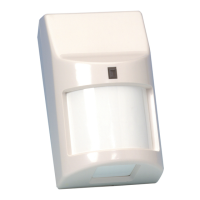
These passive infrared motion detectors are versatile wall-mounted
units employing Fresnel lenses and offering efficient protection pat-
terns for commercial and residential applications. Best coverage will
be obtained if mounting is selected such that the likely direction of
intruder motion is across the pattern.
When installed per the guidelines, the Split-Zone Optics technology in
the 998PI and 998EXPI (with tamper switch) provide reasonable false
alarm protection against pets and other animals up to 40 lbs.
SPECIFICATIONS
Detection Method: Passive Infrared.
Coverage: Pet Immune Lens,
35 ft x 45 ft (10.6m x 13.7m), 90¡.
Detection Zones: Pet Immune Lens - 30 zones
(8 long range, 7 over 7 intermediate, 4 over 4
short range).
Pulse Count: Intermediate or Standard selectable via DIP
switch.
Note: Use Standard for pet immune applications.
Detectable
Walk Rate: 0.5 - 10ft/sec (0.15 - 3m/sec).
Mount Height: 7.5 ft recommended (2.3m).
Indicator: Red LED; enabled/disabled via DIP switch.
Alarm Relay: Form A, SPST, 90mA@16V DC
15-ohm protective resistor.
Input Voltage: 10 - 16VDC (voltage reversal makes PIR
inoperative).
Current: 18mA (non-alarm), nominal.
16mA (alarm), nominal.
Standby: Power source should be capable of at least 4
hours of battery standby.
Tamper: Normally closed (with cover on), rated at .5A,
30VDC (998EXPI only).
Operating Temp.: 14¡F - 122¡F (-10¡C to +50¡C).
Operating Up to 95% RH (max.),
Humidity: non-condensing.
Dimensions: 2-5/8ÓW x 4-3/8ÓH x 2-1/8ÓD (max protrusion)
(67mm x 111mm x 54mm).
Special Instructions
for Installations Containing Pets
To take full advantage of the pet immunity in the 998PI or 998EXPI,
the following guidelines should be followed:
• Mount the center of the detector 6-1/2 to 7-1/2 feet (2.0m - 2.3m)
high and adjust the vertical angle according to Table 1.
• Set the PIR sensitivity for Standard (STD).
• Mount where animals cannot come within six feet of the detector
by climbing on furniture, boxes, or other objects.
• Do not aim the detector at stairways that can be climbed by animals.
Note: This unit will provide immunity to false alarms for an individ-
ual animal or a group of animals whose total weight is equal to or
less than 40 pounds when the room temperature is above 50¡F (10¡C).
INSTALLATION
For optimal pet immunity performance, be sure to follow all the guide-
lines described in the section ÒSpecial Instructions for Installations
Containing Pets.Ó
A. Normal Surface Mounting
Mount the unit to a firm vertical surface. The wall wiring hole should
be no more than 5/16Ó (8mm) in diameter.
1. Remove the front cover as shown in Figure 1.
2. Refer to Figure 2. Knockout holes ÒAÓ in the base are for normal
surface mounting on a wall (slide PC board up for access to bottom
holes, down for access to top holes). For corner mounting, see B.
Corner Mounting. Also break out the desired wire entry hole at
this time, marked X1 or X2 in Figure 2).
3. Feed wiring emerging from the wall through the wire access hole
near the top of the detector base. Make sure wires have sufficient
slack to allow the PC board to be moved up and down freely when
the wires are connected to the terminals on the board.
4. Mount the base. Note the mounting orientation of this detec-
tor Ð wire entry at the top, lens at the bottom! Make sure the
board is positioned so that the arrow is in line with the appropriate
setting on the graduated scale (see Figure 5 and Table 1).
5. Refer to the WIRING CONNECTIONS section before replacing the
front cover.
B. Corner Mounting
Knockout holes ÒBÓ in the base are used for corner mounting on a
wall (slide PC board up for access to bottom holes, down for access
to top holes). Mount in selected corner with 4 screws.
Note the mounting orientation of this detector Ð wire entry at
the top, lens at the bottom! Make sure the board is positioned so
that the arrow is in line with the appropriate setting on the gradu-
ated scale (see Figure 5 and Table 1).
C. Changing Lenses (if required)
1. Remove front cover.
2. Release the lens support frame located in front cover as follows:
Insert the blade of a small screwdriver between the locking tab and
the detector case in each of the four corners of the frame, and lever
each tab upward to release. See Figure 4. When all four corners are
released, remove the lens support frame.
3. Remove the existing lens and replace with the replacement lens.
The lens must be installed with the smooth side facing out-
ward. Also, the lens should be oriented with its part num-
ber on the upper right-hand side (see Figure 4). Be sure to
center the lens.
Note: Lens surface should be free of dirt, foreign matter and fin-
gerprints. Use a clean dry soft cloth to wipe lens surfaces.
4. Insert the lens support frame into its original position and then
press downward on the frame so that the lens locking tabs snap
into position in each of the four corners.