4
8 onto the drilling table 9 and milling table 7 separately. Screw the level moving bolt 27 into
sliding base 29 and make it connected with the open ended screw arbor base of the supporter
35.
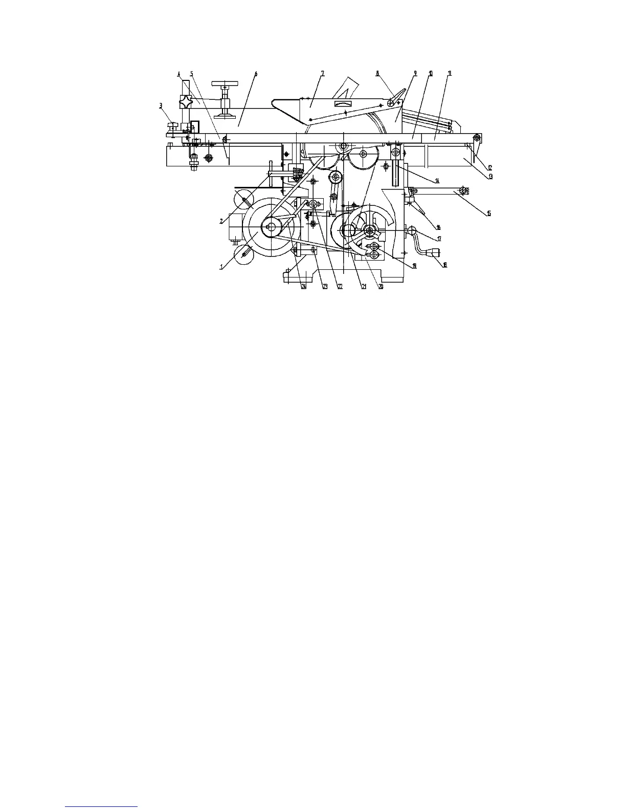
Fig.1 Overall Diagram
1.motor 2.lock b olt 3.graduated disk 4.presser 5.sliding table 6.guide7.saw hood 8.lock bar 9.splitter 10.saw
table 11.outfeed table 12.limiting rubber 13.track 14.supporter 15.press planing table 16.planing lock bar
17.auto-feeding bar 18.elevating handle 19.bolt M8×30 20.bearing base 21.V-belt A900 22.bolt M8×50 23.bolt
M8×50 24 .V-belt A800
See Fig.5, mount the square iron 12 (two pieces) on the saw table 5 with bolt 14 (four pieces)
and bushing 13 (four piece). Connect guide track 11 with square iron 12 by screw 9 (two
pieces) and press plate 10 (two pieces).
Keep the guide track 11 vertically with saw spindle. As Fig.1 showing, dismount the rubber
bushing 12,mount the crosscutting saw table 5 and keep it moving flexible on the guide track
11. Mount the dial scale 3 and presser 4.
AsshowninFig.6, mount the ruler base 3 on the front bench 1 with bolt 2 M6×12 (three
pieces). Don't fixed the bolt 2 first, put the guide 6 which connected with guide base 5 on the
ruler base 3, lock them with lock lever 4, and check if the side of the guide is parallel with the
saw blade. If it is not parallel, adjust the guide base 5 until they are parallel. After mounting,
clean the bench and clean the no painting parts with petrol or abies oil.
 Loading...