The document describes the "Ender 3 Conveyor 90 Kit," an assembly manual for converting a standard Ender 3/PRO/V2 3D printer into a sequential belt 3D printer. This kit allows users to modify their existing 3D printer to enable continuous printing, where finished objects are automatically ejected from the print bed, making it suitable for batch production or printing very long objects.
Function Description
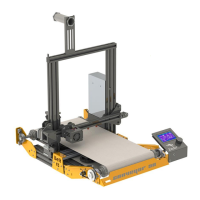
The Ender 3 Conveyor 90 Kit transforms a conventional Ender 3 series 3D printer into a belt-style 3D printer. The core functionality revolves around replacing the standard Y-axis and heatbed assembly with a conveyor belt system. This system includes rollers, a continuous belt, and a modified heatbed that moves along with the belt. The primary advantage of this conversion is the ability to print objects sequentially and continuously. As an object finishes printing, the conveyor belt advances, moving the completed print off the bed and presenting a fresh surface for the next print. This automation significantly reduces the need for manual intervention between prints, making it ideal for small-batch manufacturing or printing objects that exceed the length of a traditional print bed. The kit also includes components for adjusting the Z-endstop and integrating the new belt system with the printer's electronics and firmware.
Usage Features
The assembly manual outlines a step-by-step process for installing the kit, starting with the disassembly of the original Ender 3 printer. Users will need a set of common tools, including Allen keys, an adjustable wrench, measuring tape, a vernier caliper, and a metal ruler. For firmware flashing on older board versions, an Arduino Uno and DuPont wires are also required.
Disassembly:
The first steps involve removing the screen, the Y-axis and heatbed assembly, and the back endcaps of the 4040 aluminum bars from the bottom frame. Users are advised to save certain original parts for later use while discarding others.
Frame Preparation:
The kit includes four custom brackets (P1 C90 BACK LEFT, P2 C90 BACK RIGHT, P3 C90 FRONT LEFT, P4 C90 FRONT RIGHT) that are installed on each corner of the bottom frame using M4x8mm screws and M4 T-slot nuts. These brackets are crucial for supporting the new belt and heatbed system. The manual emphasizes using the holes on each bracket for proper alignment with the bottom frame.
Installing Belt and Heatbed System:
This is the most intricate part of the assembly.
- Preparing Rollers: Two roller assemblies are created by inserting a 12mm rod into a 40mm roller body, then securing 46mm roller caps on each end with M4x8mm headless screws. The rods must be centered within the roller bodies.
- Installing Rollers and Belt:
- Flange bearings (12mm) are inserted on both sides of one roller, and block bearings (12mm) on both sides of the other roller.
- The roller with flange bearings is installed as the front roller mount using M6x18mm screws and M6 nylock nuts. Crucially, the conveyor belt must be inserted during this step. The roller should be centered, and its position is fixed by round holes on the side plates.
- The roller with block bearings is installed as the rear roller mount using M6x30mm screws and M6 nylock nuts. Again, the belt must be inserted, but the screws should not be fully adjusted at this stage.
- Belt Tensioning: A critical step involves adjusting the screws on the rear roller to ensure proper belt tension and alignment. The distance between the external sides of the roller shafts should be approximately 480-485mm. The manual advises checking for smooth, easy, and straight belt movement without wobbling or excessive force when rolled by hand.
- Belt Motor Installation: A Timing Pulley 60T (bore 12mm GT2) is inserted onto the end of the rear roller on the left front side of the machine. The original Y-motor and pulley are then installed using M4x8mm screws and M4 slot nuts. The GT2 Timing Belt Closed Loop is placed, and both pulleys are aligned. The motor bracket is then adjusted to tension the closed-loop belt.
- Installing Heatbed:
- The original heatbed is prepared by temporarily removing the heating element and uninstalling all V-slot wheels. Users are guided to identify aligned holes on the heatbed base plate.
- Support bars (1020 ALU PROFILE 326mm) are fixed to the heatbed base plate using M5x8mm screws and M5 slot nuts. The manual notes that a 90° rotated heatbed base plate is acceptable.
- The heatbed element is reinstalled with screws and leveling nuts, compressing the springs almost halfway.
- The assembled heatbed with support bars is inserted from the left side of the machine, under the tensioned belt, ensuring the heatbed cable exits to the electronic box.
- Heatbed mounting plates are then installed using M4x8mm screws and M4 slot nuts to secure the heatbed assembly.
Finishing Installation:
The screen is reinstalled on the right side of the machine using its original M5x8mm screws, and the screen cable is reconnected. A provided face plate is installed on the front of the machine using M4x16 screws and M4 nylock nuts, maintaining a 2mm gap from the belt.
Electronics and Firmware:
All cables are reconnected to the motherboard. A supplied 1-meter stepper motor cable is used for the Y-motor if necessary. The Z-endstop is installed with its original bracket, modified by cutting a tab to allow it to go lower, and secured with an M4x8mm screw and slot nut. The X and Z axes are the only ones requiring endstops with the belt system. Zip ties are provided for cable management. The manual directs users to an external resource (Teaching Tech method on YouTube) for firmware updating, and the necessary firmware files are provided with the kit.
Calibrating Bed and Z-Endstop:
- Bed Leveling: After tensioning the belt, a large metal ruler or level is placed over the belt, supported by the rollers. Leveling nuts are used to adjust any misalignment on both sides.
- Z-Endstop Regulation: The Z-endstop support is loosened, the X-axis is brought down to the bed, and a piece of paper is placed between the nozzle and the belt. The endstop is pushed back towards the X-axis until the switch is pressed, then fine-tuned for optimal nozzle height.
Slicing (Simplify3D Settings):
The manual provides instructions for configuring Simplify3D for sequential printing with the Conveyor 90 Kit.
- Import the provided FFF profile.
- In the FFF settings window, select the "Ender 3 CONVEYOR 90" profile.
- When placing models for printing, ensure they are separated by approximately 250mm to allow the belt to release the last print.
- Copy and paste the current process for each part to be printed.
- For each process, select only the corresponding model to be printed.
- Once all models have their assigned processes, click "Prepare to Print!"
- In the "Select Processes for Printing" window, select all processes, choose "Sequential printing: object-by-object," and set the "Max height clearance" to 250mm.
- Verify in Preview mode that the simulation shows the nozzle printing one object after another.
- Finally, save the G-code to a micro SD card and print.
Maintenance Features
While the manual primarily focuses on assembly and initial setup, it implicitly highlights several areas that would require ongoing attention for optimal performance:
- Belt Tensioning and Alignment: The instructions for adjusting belt tension and ensuring smooth, straight movement are crucial not only during initial setup but also for ongoing maintenance. Users should regularly check the belt for proper tension and alignment to prevent friction problems, misalignment, and wear.
- Roller Inspection: The rollers are key components of the conveyor system. Regular inspection for wear, debris, or any issues that might impede smooth belt movement would be important.
- Heatbed Leveling: Similar to traditional 3D printers, maintaining a level heatbed is essential for good print adhesion and quality. The bed leveling process described in the manual should be performed periodically or as needed.
- Z-Endstop Calibration: The Z-endstop determines the initial nozzle height, which is critical for the first layer adhesion. Recalibration may be necessary if print quality issues arise or after any adjustments to the printer's mechanics.
- Firmware Updates: The mention of firmware updates suggests that Aditiva3D may release new firmware versions to improve functionality or address issues. Keeping the firmware updated would be a maintenance task.
- Cable Management: The use of zip ties for cable management is noted during assembly. Regularly checking cable routing and connections can prevent snags, disconnections, or damage to electrical components.
- Cleaning: While not explicitly stated, the nature of 3D printing implies that the conveyor belt and other moving parts will accumulate dust and print residue. Regular cleaning would be necessary to maintain smooth operation and prevent contamination of prints.
The Ender 3 Conveyor 90 Kit offers a comprehensive solution for users looking to upgrade their Ender 3 printer for continuous production, providing detailed instructions for both hardware installation and software configuration.