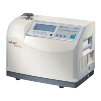
6
HARD VACUUM TEST MODE
Leak detector in stand-by mode; connect the part or
assembly to be tested to the detector.
SNIFFING TEST MODE
Leak detector in stand-by mode; connect the long
distance sniffer probe to the quick connector.
STDBYSTDBY
STDBYSTDBY
TESTTEST
TESTTEST
READY FOR CYCLE
INLET VENT : off
READY FOR CYCLE
INLET VENT : off
CYCLE
SNIFFER
SNIFFER
CYCLE
STDBYSTDBY
Starting a cycle
Ending a cycle
Starting Sniffing test
mode
Ending Sniffing test
mode
(1) As soon as the inlet pressure reaches 10 mbar (7.5
torr), the unit goes in gross leak test mode, or when the
pressure has reached 5
.
10
-1
mbar (0.37 torr), the unit
goes in fine leak test mode.
READY FOR CYCLE
INLET VENT : off
SNIFFING MODE
PLEASE WAIT…
SNIFFING MODE
Selecting a test mode C 210
(1) Read leak
value
Test cycles
STDBYSTDBY
STDBYSTDBY
TESTTEST
TESTTEST